CM602all_EJM8AESM_Service Manual.pdf - 第278页
Prepare jigs, feeders and boards. 1 to 10 Re-teach "Head Rotation Center Position." 11 Warm up the machine. 12 to 16 Test run of machine Teach 45°mounting position. 17 to 23 Teach. Place components. Recognize w…
Maintenance Adjustment
4-3-7 Mounting Position
Light Transfer-Head Assembly(3 nozzles)
This section describes the procedures for mounting position teaching.
Mounting position
correcting data
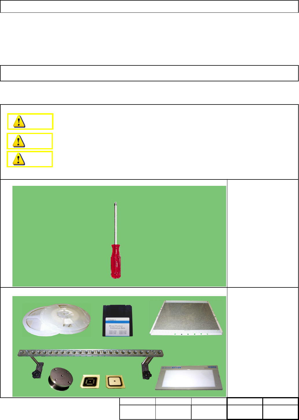
Light box 1 set
Board (240 x 216 Th:1.7)
1 pc.
QFP-jig supply-jig stand:
2 pcs.
QFP jig 30 pcs.
Nozzle 1005 6 pcs.
Low-adhesive double-
sided tape
5-hole teaching jig 1 pc.
Assembly/Adjustment
Total timeTeaching
Min.
Phillips screwdriver #2
Min.
kgs
.
90 Min.90 Min.
Part weight
・Tools
・Jig
Removal/Disassembly
Dange
r
Warning
Caution
EJM8A-E-SMA040307-A01-00
Page 4-3-7-1
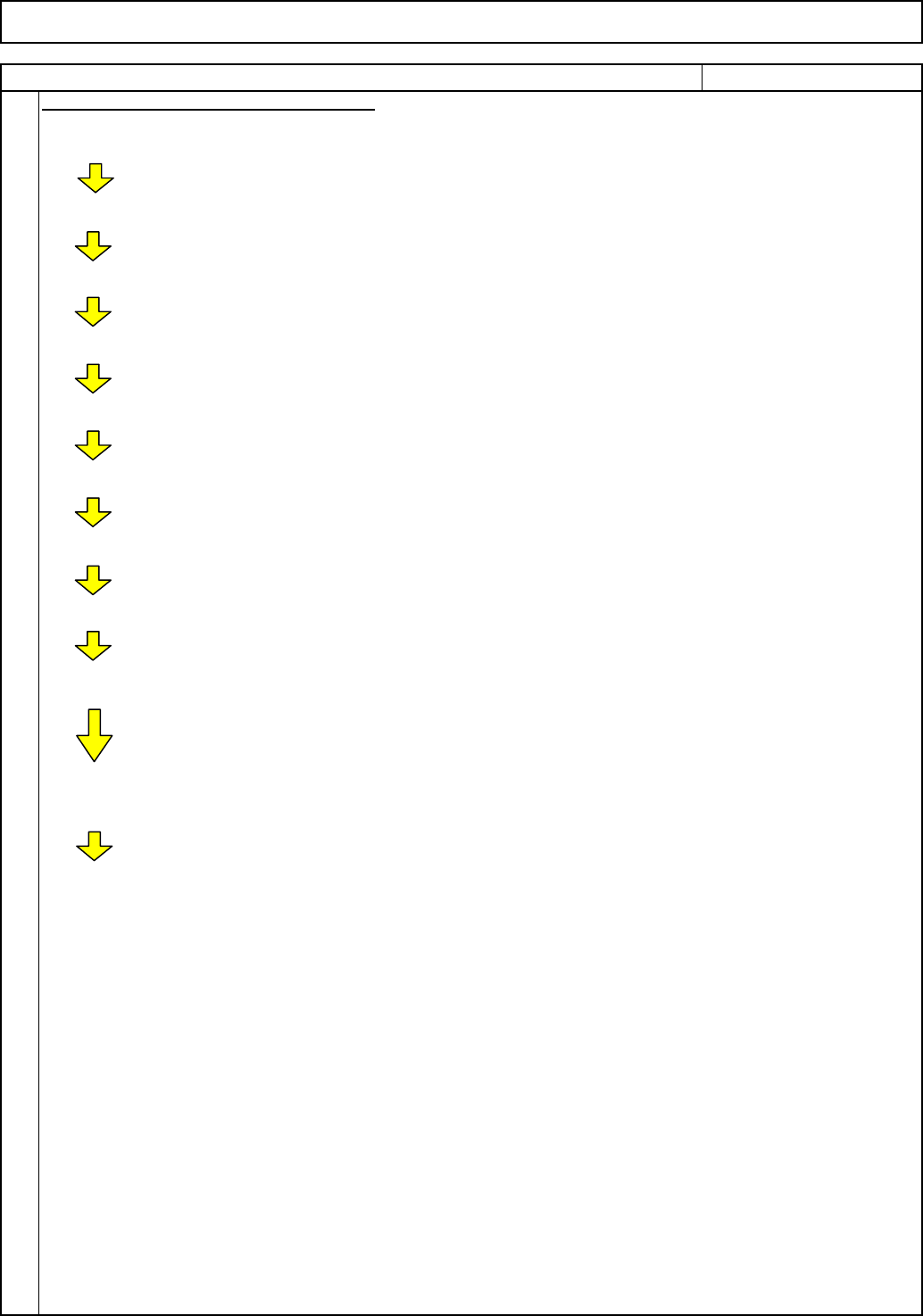
Prepare jigs, feeders and boards. 1 to 10
Re-teach "Head Rotation Center Position." 11
Warm up the machine. 12 to 16 Test run of machine
Teach 45°mounting position. 17 to 23
Teach. Place components. Recognize with
head camera. Specify offset (Auto).
Precision test (Placement accuracy test) (1) 24 to 29 Place components. Recognize with head
camera. Measure placement results.
Check precision (accuracy) (1) 30 to 31 Display the precision data.
Enter mounting position offset. 37 Calculate offset from the precision
data and enter it into "Mount position" of
Machine Parameters manually.
Precision test (Placement accuracy test) (2) 24 to 29 Test after entering the mounting position
offset.
Check precision (accuracy) (1) 30 to 31 Display the precision data.
Cpk displayed on CM602 monitor:
Guidance: 1.8 or more
(Equivalent to Cpk 1.5 or more with Panasonic
tester.)
Teach 90° mounting position.
Prepare jigs, feeders and boards. 32 to 36
Follow the procedures for 45°teaching.
Light Transfer-Head Assembly(3 nozzles)
REMARKSITEM
1
Maintenance Adjustment
Flow Chart of Mounting Position Teaching
EJM8A-E-SMA040307-A01-00
Page 4-3-7-2
Light Transfer-Head Assembly(3 nozzles)
See Section "5-8-1.
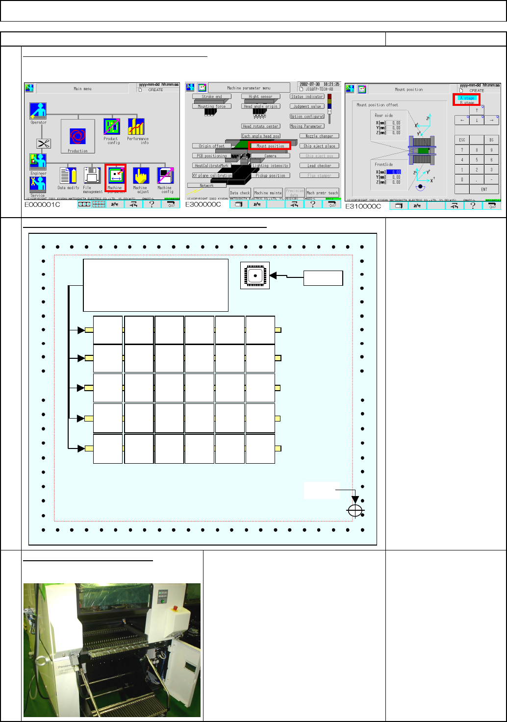
Feeder Gang Exchange
Cart Installation and
Removal"
4
Install the feeder change cart.
Double-sided tape
240×216 TH-1.7 glass
board
Enter "0" into the mounting position offset.
Maintenance Adjustment
3
REMARKS
Place double-sided transparent tape on the glass board
.
2
ITEM
80101122143164185
66
87
108
129
150
0
90
0
0
-90
180
90
0
-90
180
0
90
0
0
90
-90
180
0
-90
180
0
90
0
0
90
-90
180
0
-90
180
Place narrow double-sided tape.
If the viscosity of the tape is
excessively high, a glass chip
may be broken when removed.
Origin
QFP jig
EJM8A-E-SMA040307-A01-00
Page 4-3-7-3