CM602all_EJM8AESM_Service Manual.pdf - 第267页
Maintenance Adjustment Light Transfer-Head Assembly (3 nozzles) This section describes the procedures for determining the mounting height and for positioning the board. Tools None Jig FM-1074 Board jig 50 mm x 50 mm (wit…
Maintenance Adjustment Light Transfer-Head Assembly (3 nozzles)
Remarks
Item
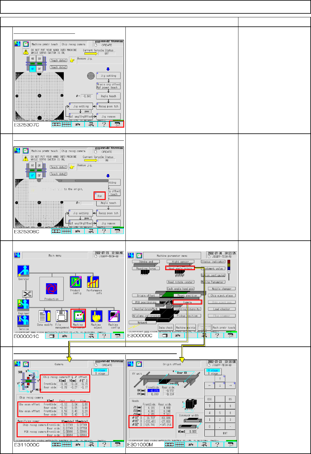
Press the [Return] key.
Press [Unlock] and [Run] simultaneously.
All axes of the selected stage return to
the origin.
The offsets are entered automatically into the screens below:
Offset range:
X, Y&θ offset
(High, Middle & Low speeds)
X :-5.0 to +5.0
Y :-5.0 to +5.0
θ :-0.1 to +1.0
* Reverse scan offset
(High, Middle & Low speeds)
Reverse scan:0.0 to 0.75
* Magnifying power
X Mag. :0.017 to 0.018
Y Mag. :0.017 to 0.018
* Head angle origin
θ: -180 to +180
16
14
15
13
EJM8A-E-SMA040304-A01-00
Page 4-3-4-5
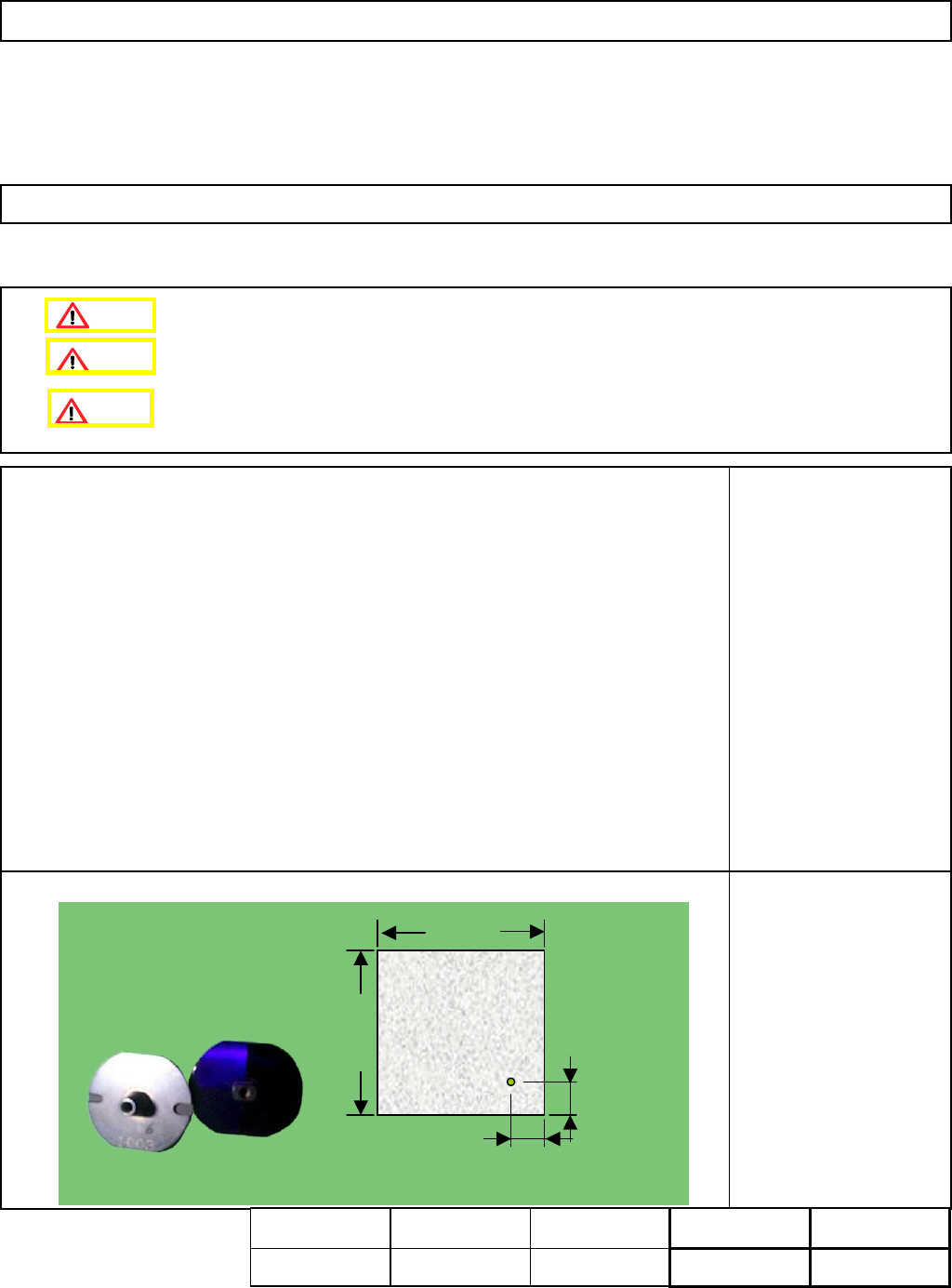
Maintenance Adjustment Light Transfer-Head Assembly (3 nozzles)
This section describes the procedures for determining the mounting height and for positioning the board.
Tools
None
Jig
FM-1074
Board jig 50 mm x 50 mm
(with a hole)
Nozzle 1003
4-3-5 Determining the Mounting Height and Positioning the Board
Remove the support pins beforehand.
10±0.05㎜
10±0.05㎜
50㎜
50㎜
t= 3.0㎜
10 +/- 0.05 mm
10 +/- 0.05 mm
50 mm
50 mm
t= 3.0 mm
Assembly
A
d
j
ustment
min.
Teaching
5 min.
Total Time Weight of
Part
Removal
Disassembl
y
min.
5 min.
kgs
Caution
Dange
r
Warning
EJM8A-E-SMA040305-A01-00
Page 4-3-5-1
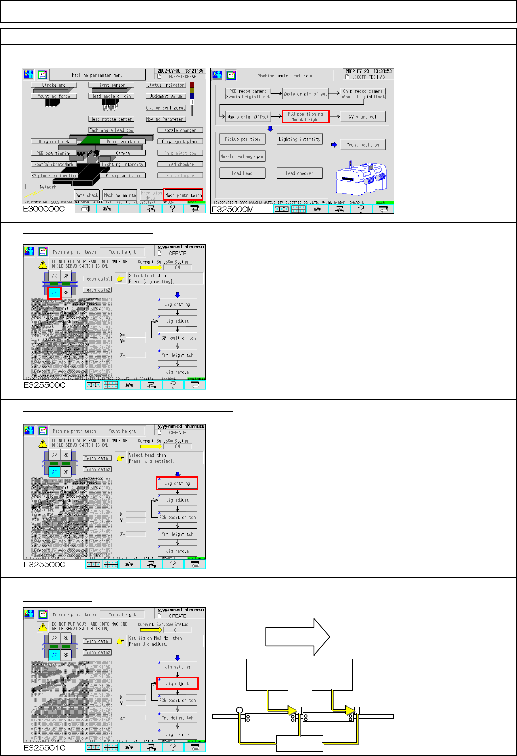
Maintenance Adjustment Light Transfer-Head Assembly (3 nozzles)
Remarks
Press [PCB positioning Mount height].
Be sure to remove the
support pins beforehand
since the width of the
conveyor is adjusted in
this step.
The conveyor will be
adjusted to a width of 50
mm.
Select the stage to be taught.
Press [Unlock] and [Jig setting] simultaneously.
Set Nozzle 1003 on
Nozzle Position 3.
Press [Unlock] and [Jig adjust]
The head moves away. The board
simultaneously.
stopper at the 2nd mounting position
moves up.
To change "Right" to
"Left," press [Jig adjust].
The 2nd mounting
position is positioned left
when you see the stage;
check that "Left" is
selected.
Item
2
3
4
1
Flow of
boards
2nd
mounting
position
1st
mounting
position
Stoppers
EJM8A-E-SMA040305-A01-00
Page 4-3-5-2