CP643 系统参考.pdf - 第116页
1.12.4 Large Parts Pick-up Check Inspection of whether or not the mounting parts have been picked up from the feeder is performed at STN2. If pickup cannot be confirmed, the line stops immediately and a device check is p…

1.12.2 Offset When Placing Parts
A total of 120 nozzles (6 nozzle types on 20 heads) can be fitted onto the machine. The
center placing point of each of these nozzles can in fact be misaligned based on the
accuracy with which the machine is assembled, the manufacturing accuracy of the parts,
or by nozzle bend. This misalignment is corrected by placing point offset values. The
different types of placing point offset values are as follows:
• Cam Speed Dependent Offset Y
Movement of the nozzle center in the Y-direction is compensated based on the cam
speed. (Cam speed 100, 90, 80, 70, 60)
• Nozzle Center Offset X
Movement of the nozzle center in the X-direction is compensated.
• Nozzle Center Offset Y
Movement of the nozzle center in the Y-direction is compensated.
• Nozzle Proper data X (A1 Place Offset X ~ T6 Place Offset X)
Amount of mechanical deviation of the X-coordinate placing point is compensated.
• Nozzle Proper data Y (A1 Place Offset Y ~ T6 Place Offset Y)
Amount of mechanical deviation of the Y-coordinate placing point is compensated.
Note: Refer to Chapter 3, “Command Descriptions“ in Part 3 “Commands” for command page
information concerning measurement of the nozzle center of rotation.
1.12.3 Tape End Display
When the supply of a part is about to run out the device number will display on the
monitor. Also, the signal tower lamp can be set to flash (the color depends on what is
entered in Proper data).
Clearing the tape end
When tape end is detected, the following actions will clear the status.
Program change: In joint mode and device change mode all devices must be cleared.
In changeover mode the tape and status of the device on the original
table must be cleared.
Parts Set switch: When parts run out during production in device change mode, once
the table has been loaded and the PARTS SET switch is set to
[COMPLETE], tape and status of the device on that table will be
cleared.
Tape End Detection switch:After the tape end the tape end sensor has detected the parts
again, the tape end status will be cleared.
Power ON: After the power has been turned on all the tape end displays will be
cleared.
Part 2 Chapter 1 Basic Operation
Edition 1.1 2-1-58 CP643E System Reference
1.12.4 Large Parts Pick-up Check
Inspection of whether or not the mounting parts have been picked up from the feeder is
performed at STN2. If pickup cannot be confirmed, the line stops immediately and a
device check is performed. If it is the end of the tape, "Parts out" is displayed. If it is not
the end of the tape, "Pickup miss" is displayed. This function is set in Part Data, allowing
it to be selected for each part type. If a part could not be picked and recovery is not set to
"error pass", the machine will attempt the recovery process at station 2 after 6 sequences.
How to set Part Data:
[PART DATA] Carrying_data
<for MCS>
Carrying_data
14. Pickup_check : This data item chooses whether or not a large part pick-up check
will be carried out.
[Example] 14. Pickup_check Stop
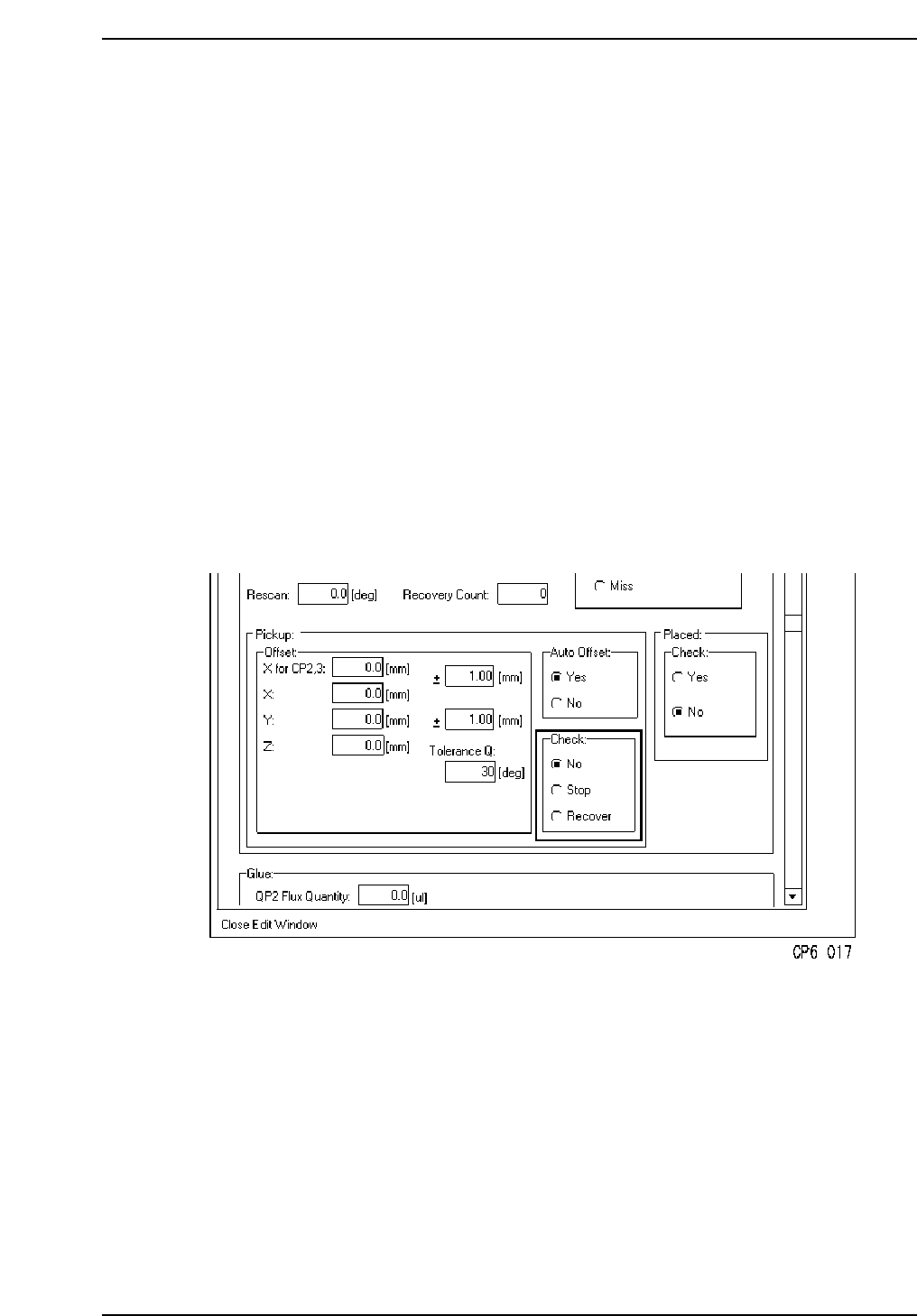
<For F4G>
1. Start the VPD.
2. Open the “Part Type Data” in the relevant part data.
3. At the [Pick up] - [Check] item, specify whether or not a large part pick-up check is to
occur.
Caution: The large parts pick-up check function is only concerned with parts whose thickness
exceeds 1 mm. The check function is not carried out for parts with a thickness
(registered in Part Data) of less than 1 mm.
Part 2 Chapter 1 Basic Operation
Edition 1.1 2-1-59 CP643E System Reference
1.12.5 Backlight and Frontlight
Vision processing is carried out at Station 6. The lighting format can be selected as either
a backlight or a frontlight format.
Details on setting the type of lighting system in Proper and Part Data follow:
[Proper]
138. Front Light : Specifies whether or not front lighting is used.
Non: . . Not fitted
Use: . . Fitted
Note: “Use” is specified in standard specification systems.
[PART DATA]
<for MCS>
Vision_data
13. Lighting : This item selects which lighting will be used.
0: Back_Light
1: Front_Light
4: Side_Light . . . . . (Option: Special front light)
Caution: “2” and “3” lighting settings are not used on the CP643E.
Note: If ‘Lighting’ is set to “2” or “3”, operation for “0” (Back_light) is carried
out.
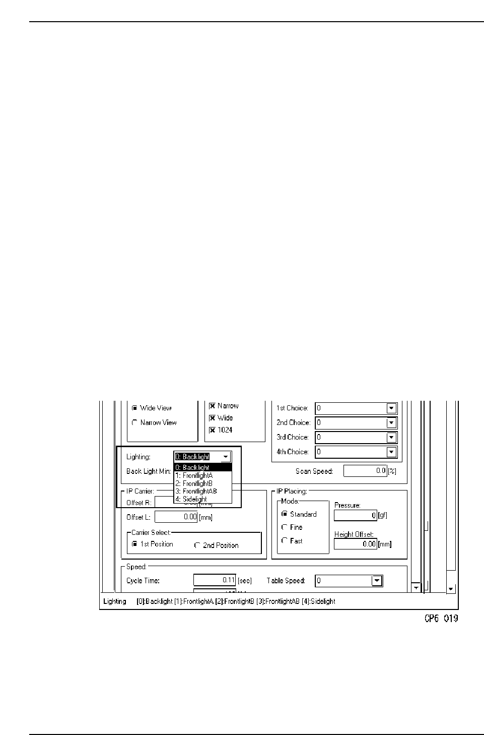
<For F4G>
1. Start the VPD.
2. Open the “Part Type Data” in the relevant part data.
3. At the [Camera] - [Lighting] item, specify the desired part image acquisition format.
Part 2 Chapter 1 Basic Operation
Edition 1.1 2-1-60 CP643E System Reference