CP643 系统参考.pdf - 第68页
1.1.7 Discarding Picked Parts On the CP-643E, data is managed for the picked parts that are at each station. In the case that distribution of part information to each station cannot be guaranteed, the picked parts will u…

1.1.6 Parts Supply Position
The following explains parts supply position settings where device tables move, when
the machine stops with parts run out, etc. during automatic operation.
(1) Joint Mode
Two modes of operation are available depending on the Proper data settings.
The item in Proper data that must be set is 142: D ESC SW.
• If this item is set to NO
If the part which has caused the alarm is a table 1 device, then the device table will
move to a device position 45 positions higher than the device number in question. The
device table will wait for parts to be supplied at that position.
If the part is set on table 2, then the device table will move to a device position 45
positions lower than the device number in question. The device table will wait for
parts to be supplied at that position.
• If this item is set to YES
If the part causing the alarm is set on device table 1, the table will move to the right
side (as viewed from the front of the machine) to its resupply position.
If the part causing the alarm is set on device table 2, the table will move to the left (as
viewed from the front) to wait at its resupply position.
(2) Device Change Mode
If the part causing the alarm is set on device table 1, the table will move to the right side
(as viewed from the front of the machine) to its resupply position.
If the part causing the alarm is set on device table 2, the table will move to the left (as
viewed from the front) to wait at its resupply position.
However, if the recovery mode is set as error stop or if the number of recovery attempts
is reached for any reason other than the set value specified in Proper data item 78. D
Change Trigger, device table change processing will not be carried out. In this case, it is
possible to select one of two supply positions using a Proper data setting. The Proper
data item to be set in this case is 142: D ESC SW.
• If this Proper data item is set to YES
The device table will move to its resupply position.
• If this item is set to NO
Device table movement will be the same as it is in joint mode.
(3) Changeover Mode
In Changeover mode there are two types of movement modes that can be set in Proper
data. The item in Proper data that must be set is 142: D ESC SW.
• If this item is set to NO
Device table movement will be the same as it is in joint mode.
• If this Proper data item is set to YES
Then the device table in question will move to its resupply position.
If device table 1 is used in automatic operation, the table will move to the right (viewed
from the front of the machine) to its resupply position. If device table 2 is used it will
move to the left (viewed from the front of the machine) and wait at its resupply
position.
Part 2 Chapter 1 Basic Operation
Edition 1.1 2-1-10 CP643E System Reference

1.1.7 Discarding Picked Parts
On the CP-643E, data is managed for the picked parts that are at each station. In the case
that distribution of part information to each station cannot be guaranteed, the picked
parts will unavoidably be discarded in order to preserve placement accuracy and
reliability.
The discarding of picked parts will be carried out in the following cases.
• After an emergency stop
After the occurrence of an emergency stop the status of the parts that have been picked
and vision processed may not have been preserved. If the cam axis is rotated manually
(using the cam handle) the picked parts will be discarded since there is a possibility
that the information for the processed parts is different from the actual status of the
parts.
• After the cam axis has been inched
In the same way mentioned above, picked parts will be discarded if the cam axis is
rotated via inching since there is a possibility that the information for the processed
parts will be different from the actual status of the parts.
• After the placing sequence order has been changed
If the number of the placing sequence or a block skip is specified by a command
operation, the picked parts will be judged as useless and thus discarded since the
placing sequence order will have changed.
• Execution of the nozzle center measurement command
Picked parts will be discarded when nozzle center measurement is carried out since
these parts are a hindrance to the execution of this command.
Part 2 Chapter 1 Basic Operation
Edition 1.1 2-1-11 CP643E System Reference
1.2 Getting Started
1.2.1 Starting the Machine
This section explains everyday start-up, reset-start and I/O check start procedures.
Normal Operation
Use the following procedure to start the machine.
1. Boot up the host computer.
This computer compiles production information transmitted from the machine in Off
Line mode.
2. Set the circuit breaker.
The machine’s main circuit breaker must be set to the ON position before the machine
can be turned on.
3. EMERGENCY STOP button check
Verify that the EMERGENCY STOP button has been pressed.
4. Turn on the power.
Press the POWER ON button on the machine operation panel to turn the machine on.
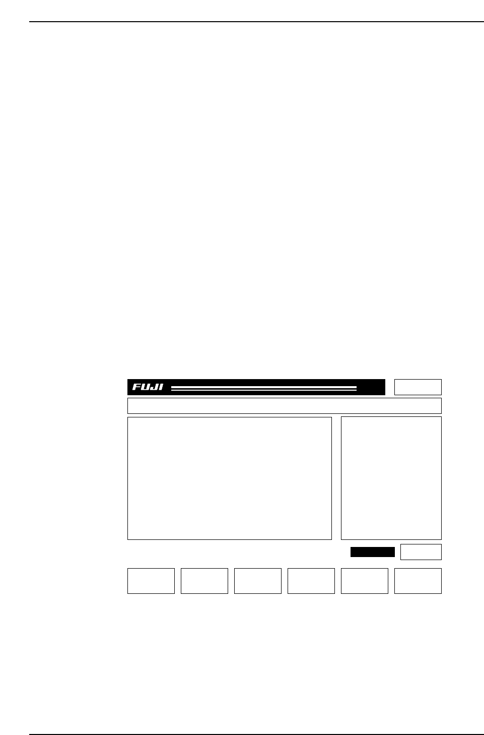
After pressing the POWER ON button, make sure that the display appears as
follows:
Page 000
Off line
MachineNot Zero-Set
Press START
CP_6.PROGRAM Prod 00000 Sche 00000
v1.10
000000000000
000000000000
jog X Y C
AUTO STEP LOADER PROGRAM SET
CP643S2006
✽
READY
LOADER
ST 1. N
ST 2. N
ST 3. N
ST 6. N
ST 7. N
ST 8. N
ST 10. N
ST 11. N
8D
7D
6D
5D
4D
3D
2D
1D
1Er****
1Er****
1Er****
1Er****
1Er****
1Er 0
1Er 0
1Er 0
STATUS
P Mode
Recovery
T Mode
Product
3 times
Joint
Part 2 Chapter 1 Basic Operation
Edition 1.1 2-1-12 CP643E System Reference