CP643 系统参考.pdf - 第361页
5.2 T race Data Outputs (For F4G Host Systems) 5.2.1 When Machine Control Keys Are Operative In F4G systems, the S/W trace and servo trace data are output to the F4G. 1. Press the CYCLE STOP button if an operation error …
5.1 Trace Data Outputs (For MCS Host Systems)
Note: A printout of the trace data list requires approximately 10 sheets of printer paper.
5.1.1 When Machine Control Keys Are Operative
1. Open the door of Control Box 1 on the machine. Refer to 1.2.1 “Description of the
Machine” of Part 1 for further details.
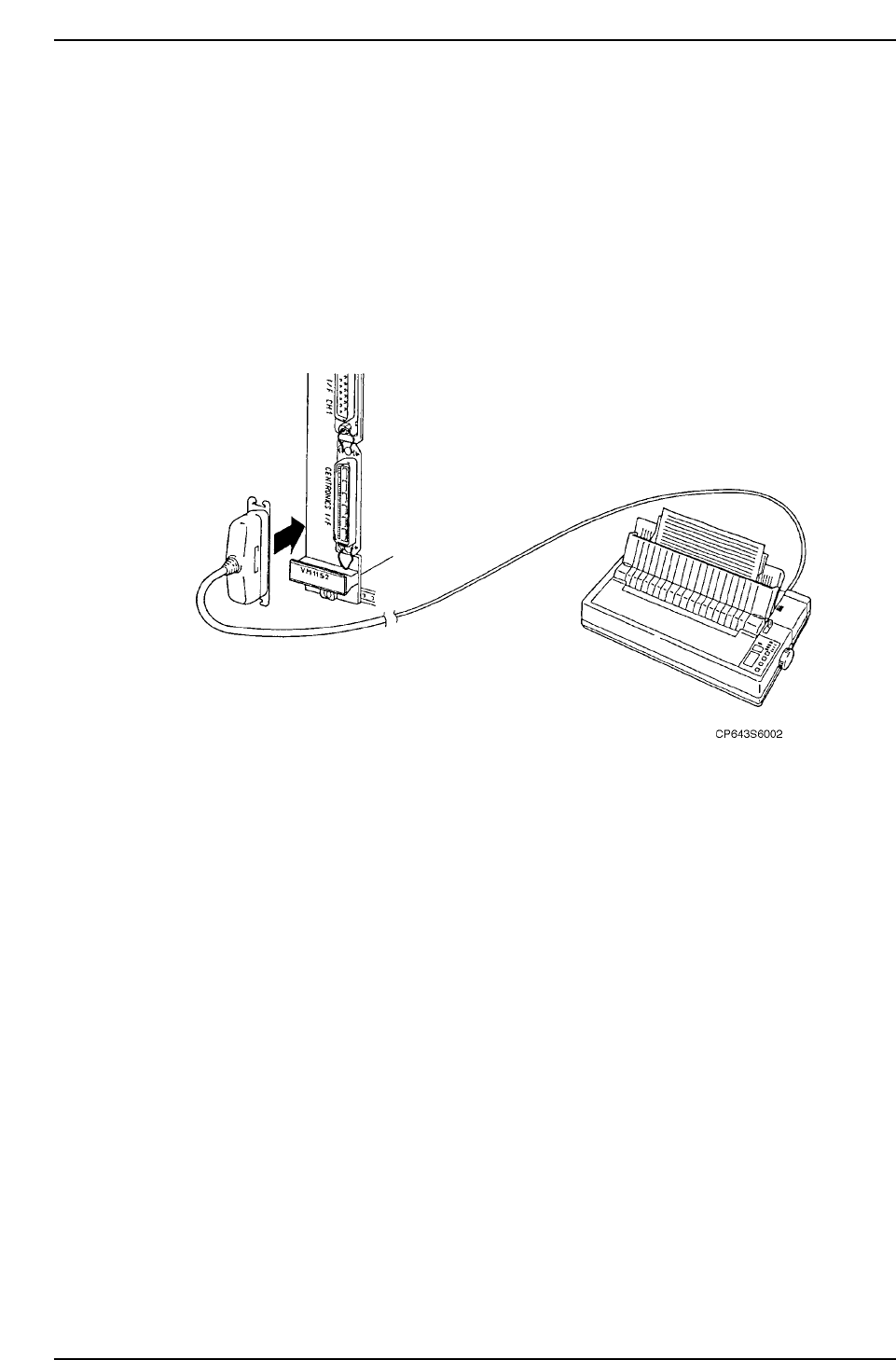
2. Find the left-most VME board, and on that board find the connector with "Printer"
next to it. Connect it with the MCS30 Printer Cable.
3. Turn the printer power ON.
4. When the CPU is running, do the following
Hold down the rapid inching key [F] and axis selection key [3]. With these keys held
down, press the axis selection key [1]. Release the keys when the printer starts.
Caution: Do not lean over the rear fence to operate the machine from the rear operation
panel. A fence alarm in the trace list will erase important command trace
information.
5. After performing the procedure above please contact Fuji.
5.1.2 When Machine Control Keys Are Inoperative
1. Perform steps 1-4 as described in section 5.1.1 above.
2. Turn the machine power off, then, with the CYCLE STOP button held down, turn the
power on again. Release the CYCLE STOP button when the printer starts.
Part 5 Chapter 5 Troubleshooting
Edition 1.0 5-5-2 CP643E System Reference
5.2 Trace Data Outputs (For F4G Host Systems)
5.2.1 When Machine Control Keys Are Operative
In F4G systems, the S/W trace and servo trace data are output to the F4G.
1. Press the CYCLE STOP button if an operation error occurs, or the RESET button if a
servo error occurs.
Caution: If the EMERGENCY STOP button was pressed, refer to section 5.2.2 “When Machine
Control Keys Are Inoperative” for the proper procedure.
2. At the VME rack, disconnect the cable from the RS232C1 port, and connect it to the
RS232C2 port.
3. At the host computer (F4G), verify the COM port number where the RS232C cable is
connected (for communication with machine).
4. End the C/C server operation.
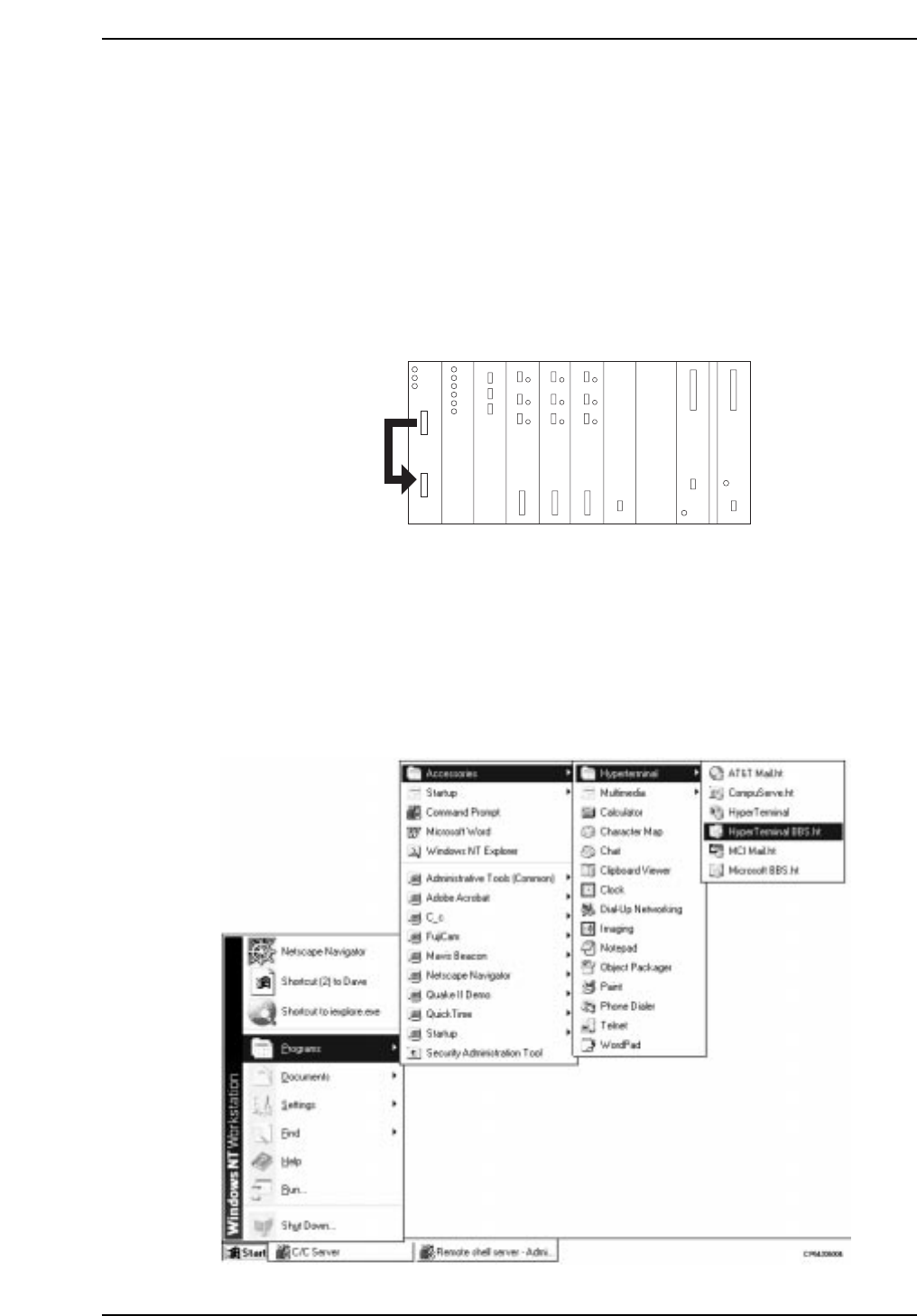
5. Start the hyper terminal. At the status bar, click [START], then select [PROGRAM] -
[ACCESSORIES] - [HYPER TERMINAL] - [HYPER TERMINAL]. The “Connection
Setting” screen then displays.
RUN
HALT
FAIL
BAT
I/O-1
R
G
B
H
V
I
RS-232C cable
CP643S6003
Part 5 Chapter 5 Troubleshooting
Edition 1.0 5-5-3 CP643E System Reference
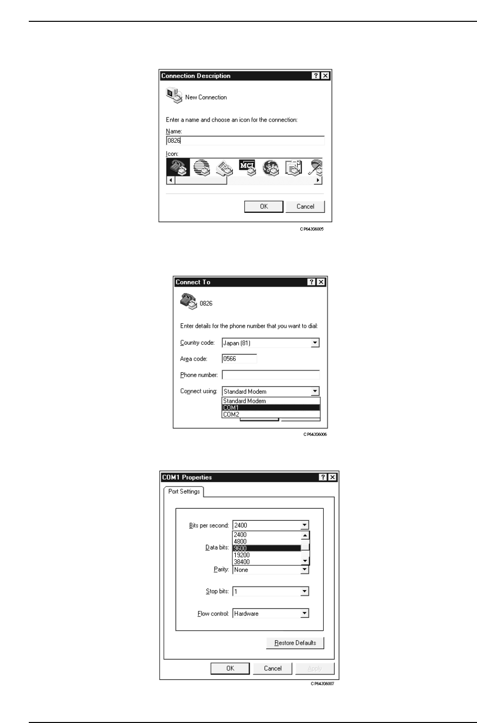
6. Enter the name of the trace data, then click [OK].
7. Select the COM port which was verified at step 3. above, then click [OK]. The “COM?
Properties” screen then displays.
8. Specify a “9600” setting at the “Bit/Sec” item (baud rate).
Part 5 Chapter 5 Troubleshooting
Edition 1.0 5-5-4 CP643E System Reference