CP643 系统参考.pdf - 第30页
1.2 Machine Components 1.2.1 Description of the Machine The names of each part of the machine for the CP-643E series machines that are mentioned in this manual are given in the figure below. (1) Front View of the Machine…
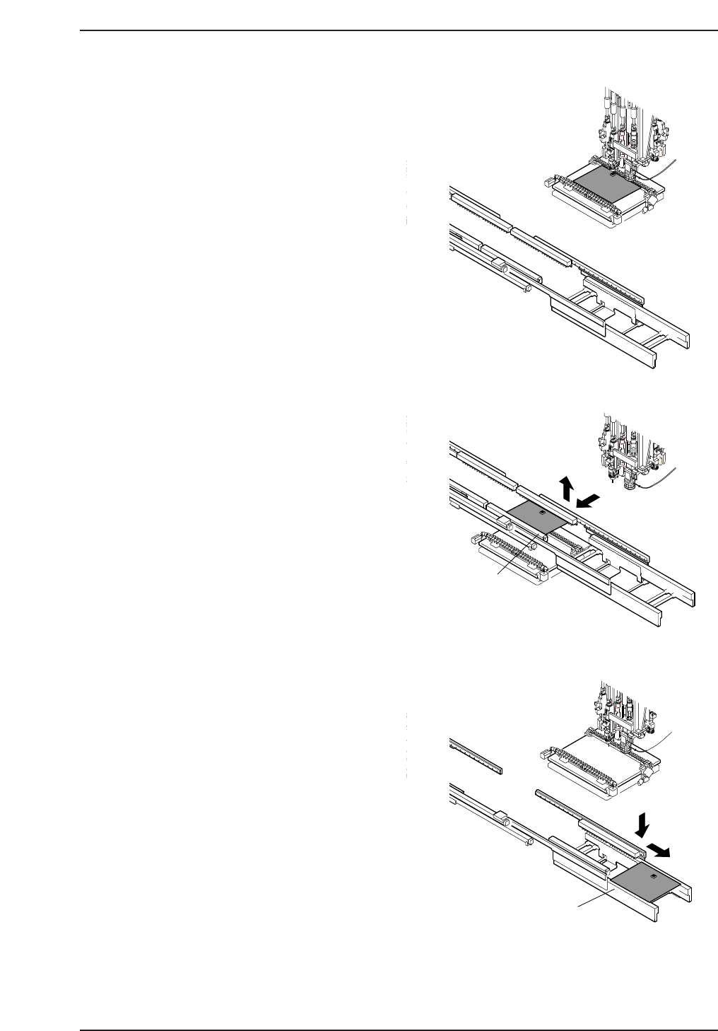
10. Placement
Turret and XY-table movement
coincide at station 11 for part
placement.
When the XY-table has reached the
placement position and the part is
placed (J).
11. Reverse rotation
At stations 12 and 13 the nozzle holder
is returned to its origin position.
Steps 5 trough 11 are repeated until
production for the panel(s) currently
held by the XY-table is complete.
12. Panel unclamping and
changeover
When population of the current
panel(s) is complete, the XY-table
moves to the out-carrier.
At this position, the XY-table is raised
and the panel is transferred from the
table to the out-carrier (K).
The out-lifter subsequently moves to
the out-conveyor and the panel is
lowered onto the out-conveyor via the
out-lifter.
When the completed panel touches the
stopper on the out-conveyor, a panel
unload request is issued to the next
machine. If a panel load request signal
is received from the next machine, the
panel is unloaded (L).
Note: No changes occur in part handling at station 2, 4, 5, 7, 8, 9, 14, 15 and 20.
This explanation describes single panel production. Double panel production is the same,
except for the use of stoppers to position the second panel at the in- and out-conveyor.
G
ot
o
&
W
il
l
ia
m
'
s
L
a
b
o
r
at
ri
e
s
C
G
o
t
o
&
W
i
llia
m
's
L
a
b
o
ra
trie
s
J
K
L
Out-carrier
Out-conveyor
CP643S1046
Part 1 Chapter 1 Machine Overview
Edition 1.1 1-1-3 CP643E System Reference
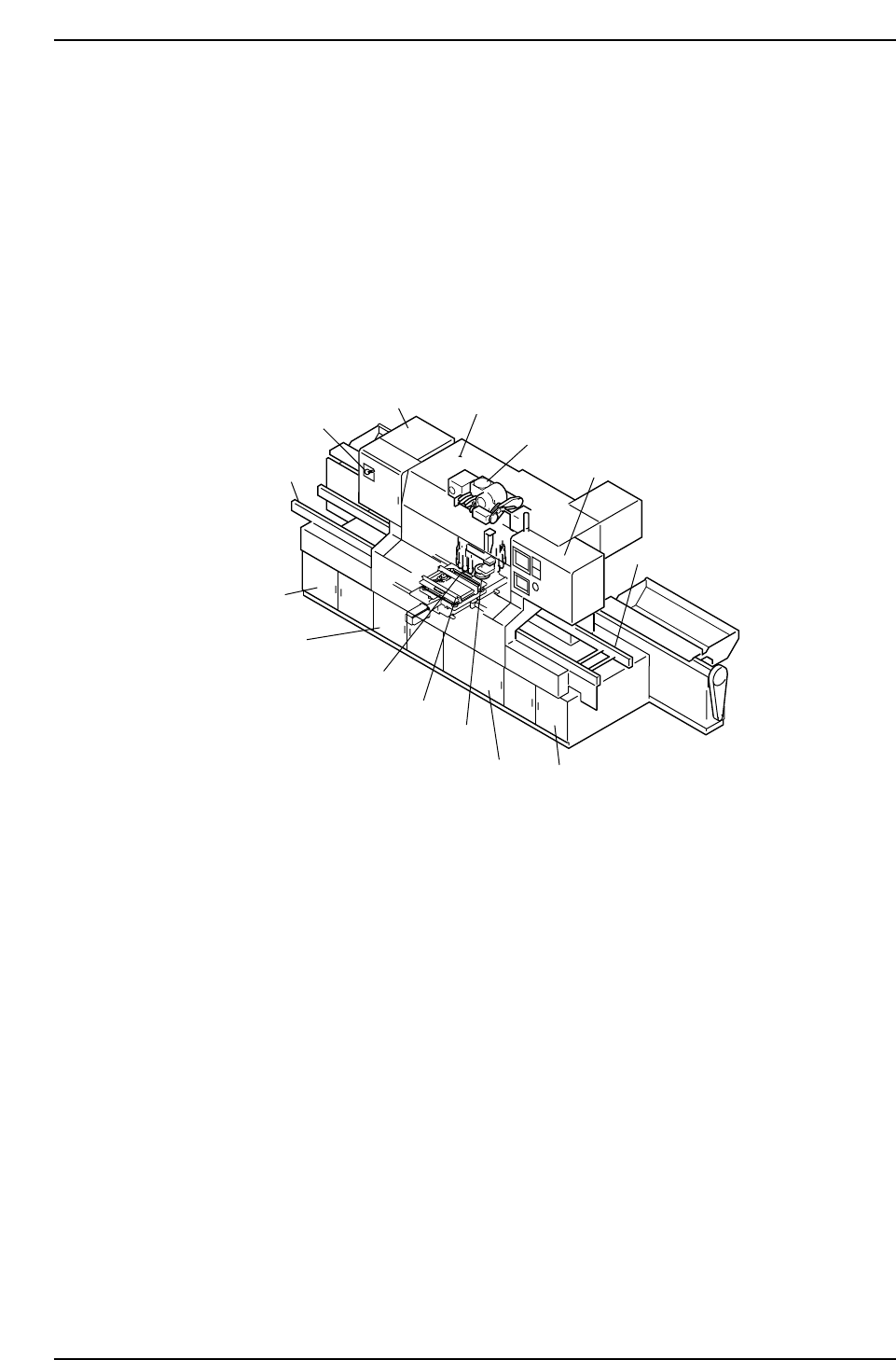
1.2 Machine Components
1.2.1 Description of the Machine
The names of each part of the machine for the CP-643E series machines that are
mentioned in this manual are given in the figure below.
(1) Front View of the Machine
Servo box 2
Servo box 1
XY-table
Control box 1
Control box 2
Out-conveyor
Breaker
In-conveyor
Placing head
Operation box 1
Optical correction camera
Index Unit
Cam box
Oil cooler
CP643S1001
Part 1 Chapter 1 Machine Overview
Edition 1.1 1-1-4 CP643E System Reference
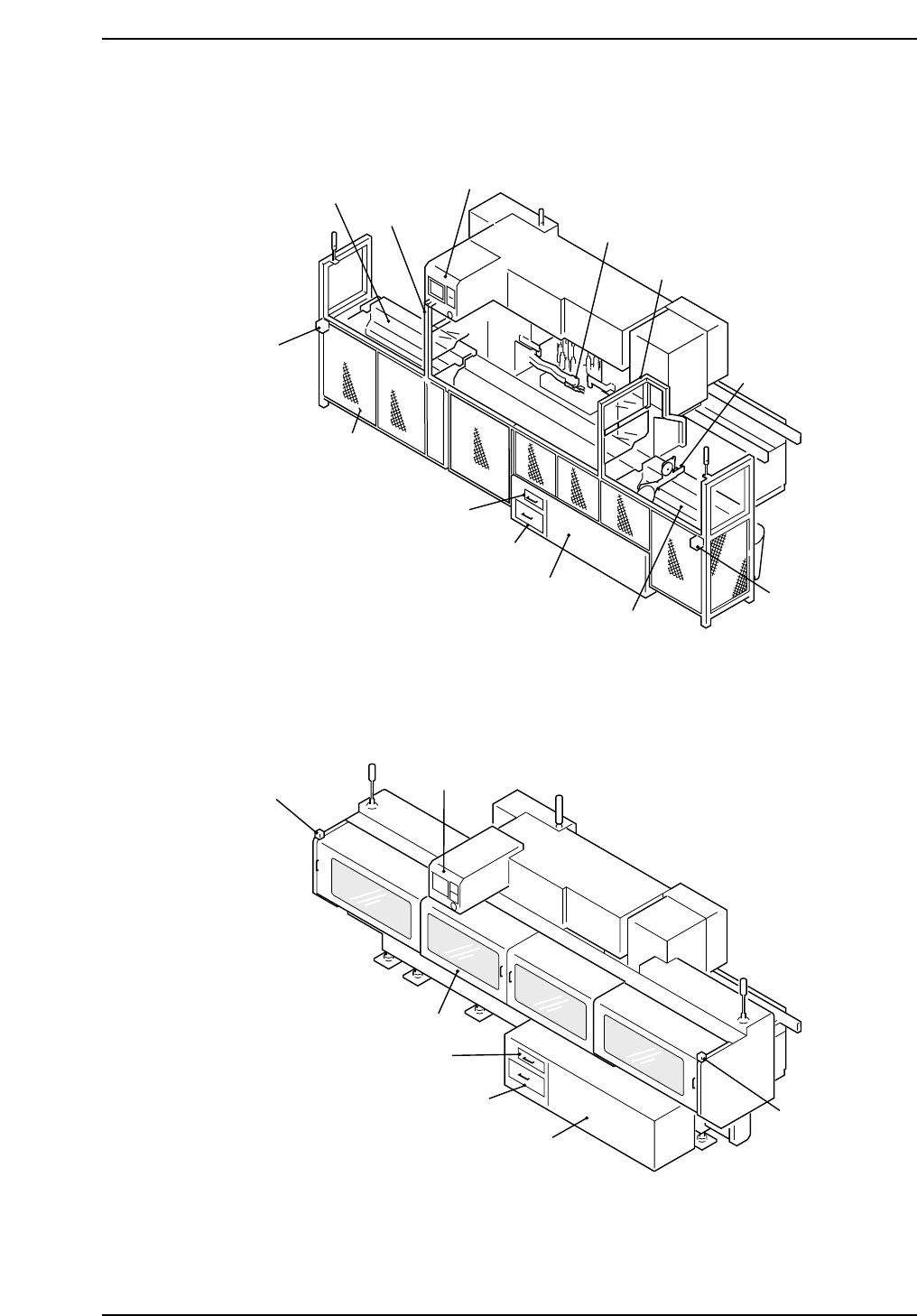
(2) Rear View of the Machine
<Models with Fence>
<Models with Rear Cover>
Filter
Waste tape box
Operation box 2
Noise reduction box
Rear cover
CP643S1003
Parts set
complete switch
Parts set
complete switch
Noise reduction box
Filter
Waste tape box
Rear fence
Shutter 1
Operation box 2
Shutter 2
Device table 2
Feeder
Waste tape cutter
Device table 1
CP643S1002
Parts set
complete switch
Parts set
complete switch
Part 1 Chapter 1 Machine Overview
Edition 1.1 1-1-5 CP643E System Reference