CP643 系统参考.pdf - 第129页
Just as with device check and nozzle check, the START button will not be enabled if the stopper position is not set. The following screen appears when the board distance check function is entered. Action of the function …

1.17 Changeover
1.17.1 Changeover
• If the distance between the right edges of the 1st and 2nd boards is changed, perform
the adjustments described below as required for the boards in question.
• Position of the reference pin of the second board and the positions of the follow-up
pins for the first and second board.
• Mid-stopper position for the second board (when two-board production)
• The maximum board width for 2-board production becomes the (maximum board
length - board distance) / 2.
The maximum board size is (Maximum board width, 457 mm (L) - Board distance, 15
mm) / 2 = 221 mm, and set at 220 mm in the specifications.
The board distance is the gap distance between the first board and the second board,
and in the design, the minimum board distance is 15 mm. Also, since the stopper for
the second board on the conveyor is the movable type, the board distance can vary.
However, if the board's length L is less than 80 mm, the board distance, in the case that
second board production is performed, becomes 90 mm minus board length due to
limitations in
the range of movement of the second board stopper on the conveyor. For
example, if the board's length L is 50 mm, the board distance is 95 mm - 50 mm = 45 mm.
• The first production board size is 50 (W) 50 (L) to 356 (W) 457 (L) mm.
• The second production board size is 50 (W) 50 (L) to 356 (W) 220 (L) mm.
• Since board clamping references the bottom surface, adjustment of the height of the
backup pins is not necessary even if the thickness of the board changes.
• Conveyor width change
Advance the out-carrier, raise the XY-table at the unloading position and then link the
conveyors. (An adjustable rail engage check is carried out when the XY-table rises.)
A change in the width of the main conveyor on the XY-table is carried out as a follow
up to the out-carrier. The width of the in-conveyor, in-carrier and out-carrier are also
changed after being joined to the out-conveyor.
1.17.2 Function for Checking the Distance Between Boards
This function performs a check to determine whether the mid-stopper is at a position
that matches the production program and therein checks the distance between the first
and second board.
When the program is transmitted to the foreground or after a program change has been
carried out, the distance between board 1 and board 2 is checked when automatic
operation is entered.
The display for checking the distance between boards is entered when one of the
following conditions applies.
• Immediately after a reset-start.
• If the PCB_Distance differs between the previous program and current program after a
program change.
The following Proper data item must be set to operate this function.
pcb_distance_check_sw
Specify whether a check of the stopper position is to be carried out (Yes or No).
The default setting is “Yes”.
Part 2 Chapter 1 Basic Operation
Edition 1.1 2-1-71 CP643E System Reference
Just as with device check and nozzle check, the START button will not be enabled if the
stopper position is not set.
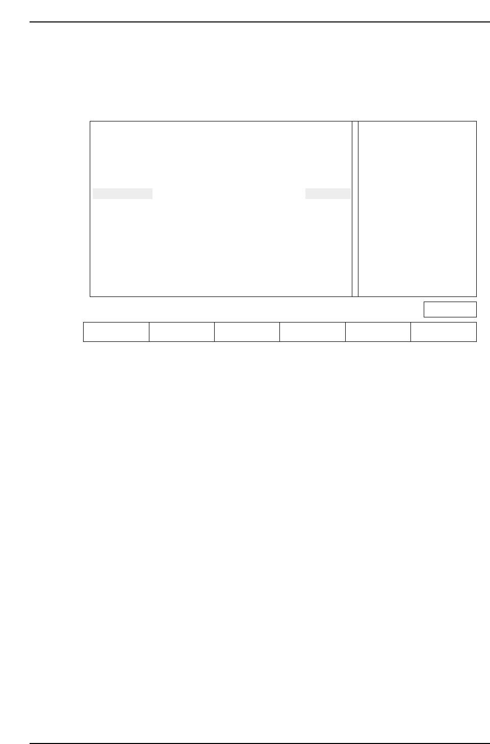
The following screen appears when the board distance check function is entered.
Action of the function keys
SET : Press this key after moving the mid-stopper position or reference pin
position to the specified position. This completes the setup.
▲ : Press to move the cursor up
▼ : Press to move the cursor down
RETURN : Press to return to the command selection screen (Page 000).
Note: The information related to the reference pin will only display if the reference pin specification
has been set in Proper data.
For reverse flow machines the display message is as follows.
“Extend IN-carrier when changing conv width
Raise main conv at IN-conv loading position”
When automatic changeover is carried out using HELPS, the above mentioned message
does not display since the conveyors are linked automatically (both standard and reverse
flow).
Check the position of the mid-stopper
Check the position of the reference pin Ready
Press [SET] to define pcb_distance
Extend OUT-carrier when changing conv width
Raise main conv at OUT-conv loading position
IN-cov
OUT-cov
Ref pin
UNSET
UNSET
UNSET
M/C
PCB_DISTANCE
-150.00 mm
-150.00 mm
-150.00 mm
PROGRAM
PCB_DISTANCE
-160.00 mm
-160.00 mm
-160.00 mm
Page 000
SET ▲▼ RETURN
CP643S2037
Part 2 Chapter 1 Basic Operation
Edition 1.1 2-1-72 CP643E System Reference
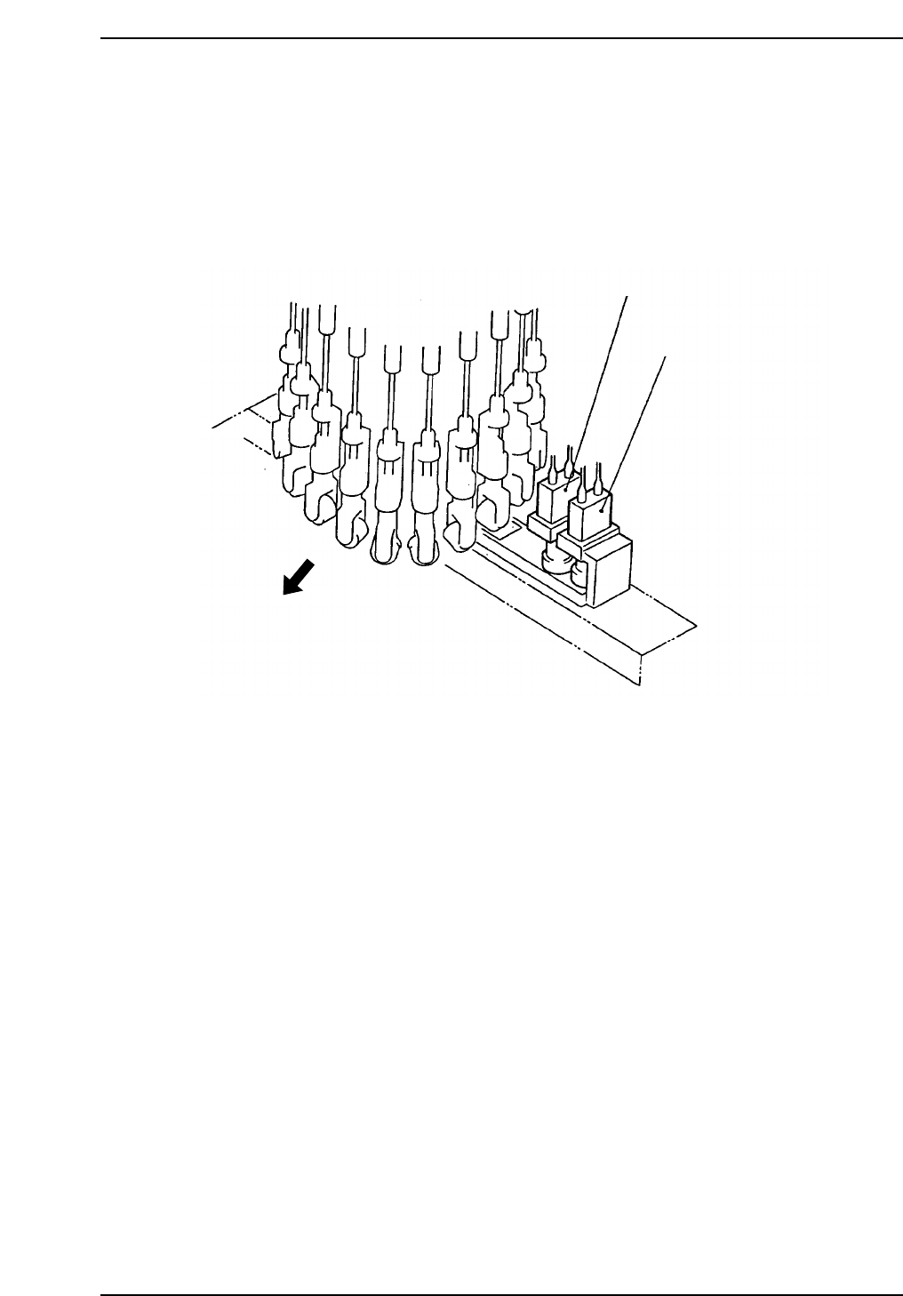
1.18 Two Camera System
Because some parts require highly accurate placing, the vision processing system uses
two cameras: a wide view and a narrow view camera.
1.18.1 Camera Mounting Position
The position of cameras are shown below.
Wide View Camera
Machine front
Narrow View Camera
CP643S2038
Part 2 Chapter 1 Basic Operation
Edition 1.1 2-1-73 CP643E System Reference