CP643 系统参考.pdf - 第35页
Inching Axis Selection Key [1] Inching axis display: X, Y, C Inching keys: [ ← ] X-axis, negative direction [ → ] X-axis, positive direction [ ↑ ] Y-axis, positive direction [ ↓ ] Y-axis, negative direction [ ] C-axis, c…
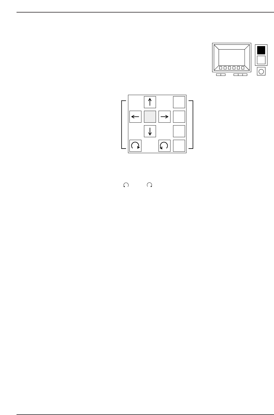
(2) Inching Keys
The “inching” function is used to move individual servo axes manually.
The inching keys are used to select the inching axes, and to
carry out inching along the selected axes.
a: Arrow keys (↑, ↓, →, ←, , and )
These keys are used to perform the inching operation. Some arrow keys are invalid
when certain inching axes are selected.
b: Inching axis selection keys (1 to 4)
These keys are used to select an axis for inching.
c: Rapid inching key (F)
Press this key and an inching key simultaneously to inch the axis rapidly.
Only those axes which are currently selected by the inching axis selection keys can be
inched.
About Inching
Inching can be carried out at any time except during machine operation or Proper data
measurement. However, it is not possible to inch all of the axes at the same time.
The axes selected by each of the inching axis selection keys and the corresponding
displays are listed below.
If the cam axis is inched when parts have been picked, those picked parts will be
discarded.
1
F 2
3
4
(a) (b)
CP643S1010
(c)
CP643S1009
Part 1 Chapter 1 Machine Overview
Edition 1.1 1-1-8 CP643E System Reference
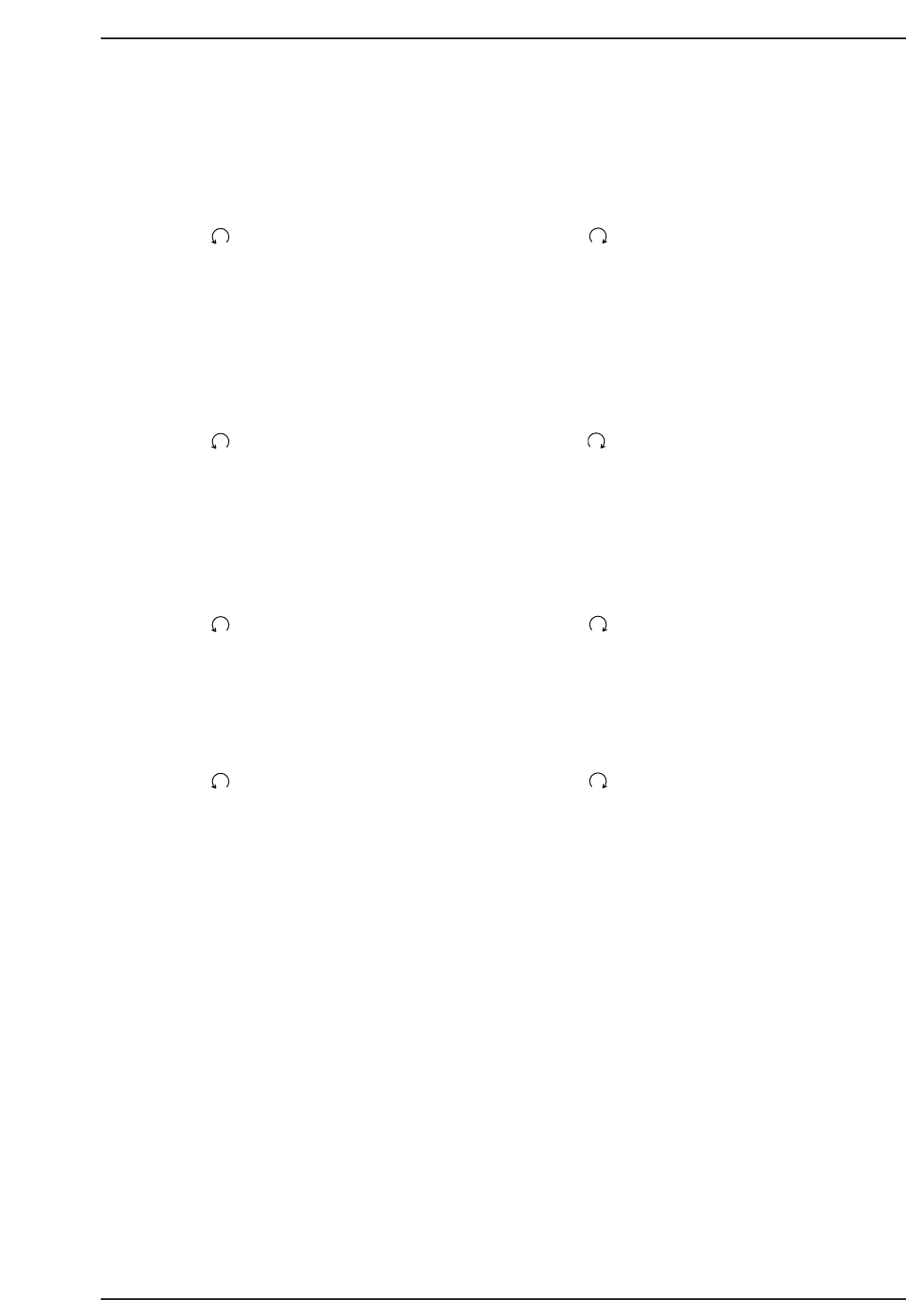
Inching Axis Selection Key [1]
Inching axis display: X, Y, C
Inching keys:
[←] X-axis, negative direction [→] X-axis, positive direction
[↑] Y-axis, positive direction [↓] Y-axis, negative direction
[ ] C-axis, counterclockwise direction [ ] C-axis, clockwise direction
Inching Axis Selection Key [2]
Inching axis display: D1, Z, FQ
Inching keys:
[→] D1-axis, positive direction [←] D1-axis,negative direction
[↑] Z-axis, positive direction [↓] Z-axis, negative direction
[] Fθ-axis, counterclockwise direction [ ] Fθ-axis, clockwise direction
Inching Axis Selection Key [3]
Inching axis display: D2, FRQ
Inching keys:
[→] D2-axis, positive direction [←] D2-axis,negative direction
[] FRθ-axis, counterclockwise direction [ ] FRθ-axis, clockwise direction
Inching Axis Selection Key [4]
Inching axis display: NC
Inching keys:
[ ] NC-axis, counterclockwise direction [ ] NC-axis, clockwise direction
Notes:
1. D1- and D2-axis inching is possible only when the shutter is at its UP limit position.
2. To change the inching speed, use the following command sequence to select the desired
axis, then enter the desired speed from the numeric keypad.
[SET] - [SERVO] - [SPEED] - [▲] / [▼]
3. Always verify that the axis to be moved is free of interference before performing an inching
operation.
When the XY-table is at either the loading or unloading position, there are restrictions on
the Z-axis inching direction depending on the status of the carrier and main lifter.
Part 1 Chapter 1 Machine Overview
Edition 1.1 1-1-9 CP643E System Reference

Using the Special Key
The functions listed below can be carried out using the special function key. However,
these functions can be carried out only when the main operations of the inching keys are
enabled (i.e. these functions cannot be carried out when the inching keys have been
disabled due to machine operation or Proper data measurement).
Turning the light source for the mark camera on and off.
Perform the following steps:
1. While holding down the rapid inching key [F], press axis change key [4].
2. The mark camera lamp turns on. Perform this operation again to turn the mark
camera lamp off.
Caution: Do not keep the light on for long periods of time, as the life span of the bulb will decrease.
Part 1 Chapter 1 Machine Overview
Edition 1.1 1-1-10 CP643E System Reference