CP643 系统参考.pdf - 第27页
1. Machine Overview 1.1 Machine Movement During Operation The explanation below provides a step-by-step description of machine movement from the point a panel is loaded onto the in-conveyor to the point where the panel i…

Part 1
Introduction
1. Machine Overview
1.1 Machine Movement During Operation
The explanation below provides a step-by-step description of machine movement from
the point a panel is loaded onto the in-conveyor to the point where the panel is unloaded
from the out-conveyor.
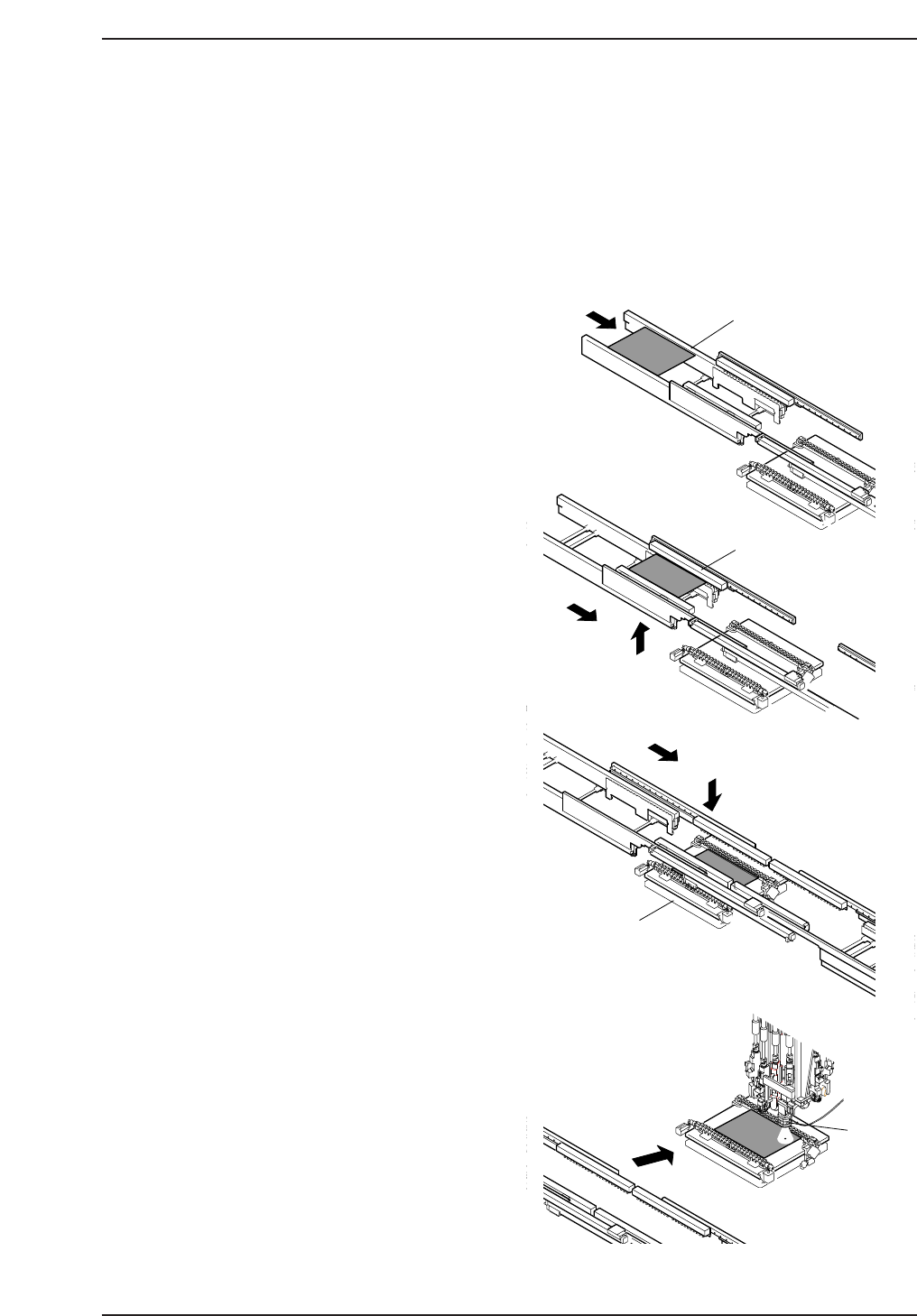
1. Panel check
When the START button is pressed, a
check is made of whether a panel is
present on the conveyor.
If no panel is held by the in-conveyor,
the in-carrier, or the XY-table, a panel
request signal is sent to the previous
machine.
If a panel is available, the panel is
loaded as detailed in step 2, after
preparations for the unloading of the
panel held at the out-conveyor are
complete. If a panel is already present,
mark reading is performed as detailed
in step 4.
2. Panel loading
When a panel available signal is
received from the previous machine in
the line, a panel is loaded onto the in-
conveyor (A).
The loaded panel is then lifted and
transferred to the in-carrier (B), at
which point advance pick-up is
performed as detailed in step 3.
3. Advance pick-up
The machine picks up parts in advance,
while the panel is transferred from the
in-carrier to the XY-table (C).
4. Mark reading
After the panel has been loaded onto
the XY-table, the panel is positioned
under the mark read camera and the
fiducial marks are read (D).
A
B
C
D
G
o
to
&
W
illia
m
's
L
a
b
o
r
a
tr
ie
s
In-conveyor
In-carrier
XY-table
XY-table
CP643S1044
Part 1 Chapter 1 Machine Overview
Edition 1.1 1-1-1 CP643E System Reference
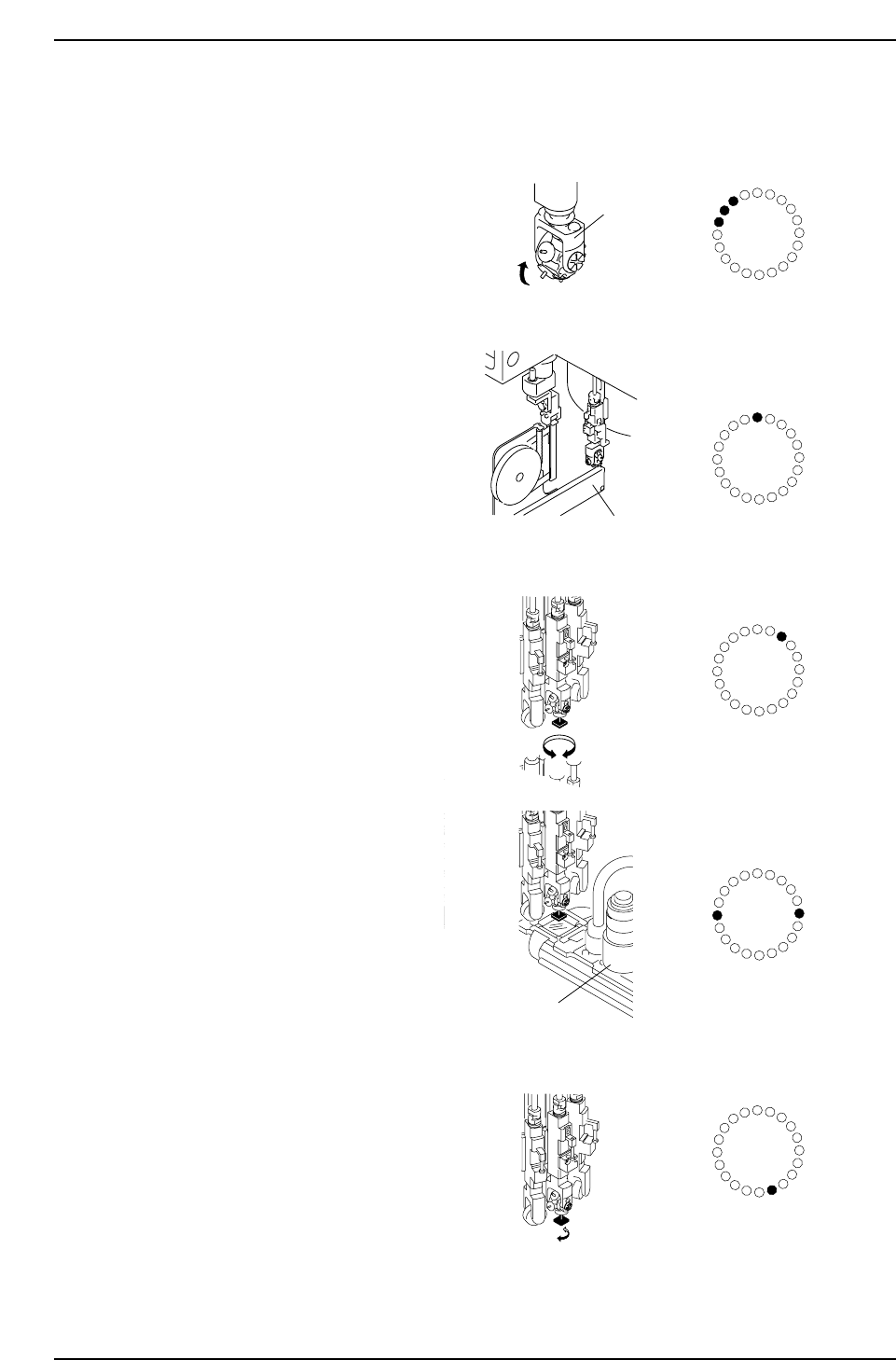
5. Nozzle change
At station 17 a check is performed
to establish which nozzle is
currently down. If a different
nozzle is required for pick-up, the
rotary head is indexed (E) at
station 18 until the required
nozzle is in position. To confirm
that the correct nozzle is selected,
another check is performed at
station 19.
6. Pick-up
When the selected nozzle moves
to station 1 the cam speed is
adjusted and brought to a halt
when the nozzle is at the pick-up
position (F).
7. Pre-rotation
To reduce cycle time and placing
accuracy, parts that need to be
placed at large angles are pre-
rotated prior to fine theta
adjustment (G). Pre-rotation is
performed at station 3.
8. Part inspection
At station 6 the part is inspected
by the CCD camera (H).
Depending on the size of the
inspected part, either the narrow
or the wide view camera is used
for inspection.
Parts which do not pass
inspection at station 6 are not
placed and are dropped into the
reject parts box at station 16 after
which recovery is performed in
accordance with the settings
made at the machine.
9. Fine Theta Adjustment
At station 10 final adjustments are
made to the part angle on the
basis of data obtained from the
mark and parts cameras (I).
E
F
G
H
I
Nozzle holder
Feeder
Parts camera
ST1
ST2
ST3
ST4
ST5
ST6
ST7
ST8
ST9
ST10
ST11
ST12
ST13
ST14
ST15
ST16
ST17
ST18
ST19
ST20
ST1
ST2
ST3
ST4
ST5
ST6
ST7
ST8
ST9
ST10
ST11
ST12
ST13
ST14
ST15
ST16
ST17
ST18
ST19
ST20
ST1
ST2
ST3
ST4
ST5
ST6
ST7
ST8
ST9
ST10
ST11
ST12
ST13
ST14
ST15
ST16
ST17
ST18
ST19
ST20
ST1
ST2
ST3
ST4
ST5
ST6
ST7
ST8
ST9
ST10
ST11
ST12
ST13
ST14
ST15
ST16
ST17
ST18
ST19
ST20
CP643S1045
ST1
ST2
ST3
ST4
ST5
ST6
ST7
ST8
ST9
ST10
ST11
ST12
ST13
ST14
ST15
ST16
ST17
ST18
ST19
ST20
Part 1 Chapter 1 Machine Overview
Edition 1.1 1-1-2 CP643E System Reference