CP643 系统参考.pdf - 第83页
(2) Main Points The nozzle center measurement is an operation designed to obtain a compensation value for the nozzle center of each nozzle. If this measurement is not carried out, the vision processing of parts that are …
1.4.2 Nozzle Center Measurement
In order to achieve high placing accuracy, the machine stores data on the center of
rotation, the amount of bend and other such data for each nozzle. The measurement of
these compensation data is called nozzle center measurement. Nozzle center
measurement is an indispensable part of being able to carry out highly accurate
placement.
This chapter provides an explanation of the nozzle center measurement.
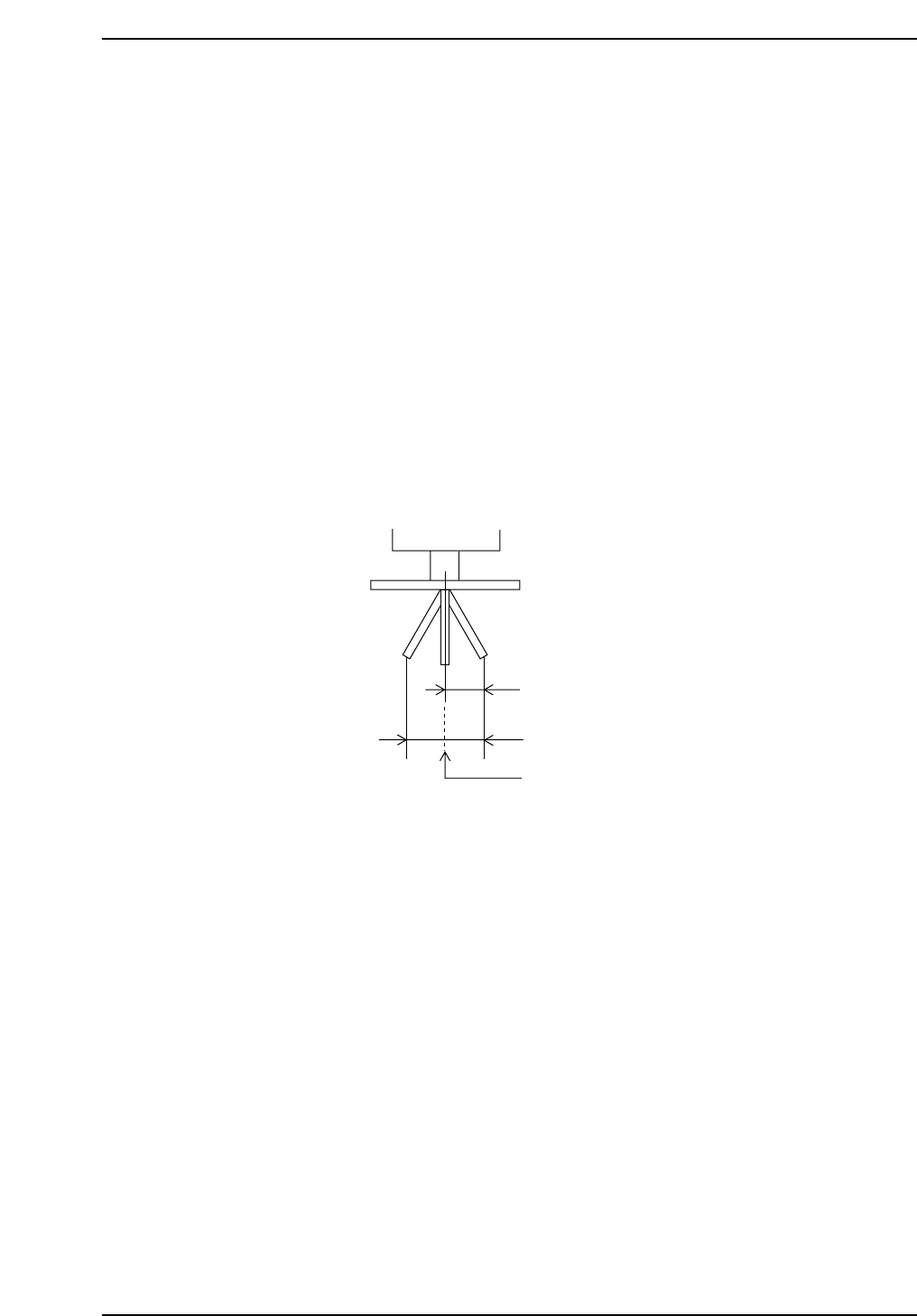
(1) An Explanation of Nozzle Center Measurement
Nozzle center measurement carries out a measurement of the holder's rotation center.
The amount of bend in the nozzle, the nozzle tip diameter and the brightness of the
nozzle back light disk are also measured at the same time.
The distance from the rotation center to the nozzle tip is calculated. The nozzle bend is
compared to the amount of allowable bend (bend tolerance) and a decision is made.
When the nozzle is rotated 180° this yields the maximum amplitude of the nozzle tip and
thus the maximum amount of bend tolerance.
The nozzle center measurement is carried out twice on a single nozzle. The first
measurement looks at the current nozzle tip position. The second measure of the nozzle
tip position is carried out after the nozzle has been rotated 180°. During this second
measurement the maximum amplitude of the nozzle tip, the center and the amount of
nozzle bend are calculated.
Image processing for a single nozzle is carried out using both the wide view camera and
the narrow view camera since the camera resolution, field of vision and other such
variables are different.
Note: The narrow view camera (in effect the image is magnified by this camera) has a small area
image and is not used to perform nozzle center measurement on nozzles with a diameter
2.0 mm or greater.
Amount of allowable bend
Maximum amplitude
of the nozzle tip
Nozzle center of rotation
CP643S2010
Part 2 Chapter 1 Basic Operation
Edition 1.1 2-1-25 CP643E System Reference

(2) Main Points
The nozzle center measurement is an operation designed to obtain a compensation value
for the nozzle center of each nozzle. If this measurement is not carried out, the vision
processing of parts that are to be placed will not be exact. It is necessary to carry out
nozzle center measurement in the following cases.
When nozzle center results show that the Head A #1 nozzle is defective (NG)
Placement accuracy maybe affected if production is carried out regardless of this result.
Even if the No.1 nozzle is not used in the program, placement accuracy is still affected.
This is because the Head A #1 nozzle is used as a reference for all center measurement
offset values. Enter production only when an "OK" result is obtained for the Head A #1
nozzle.
After camera Proper data has been remeasured
When the camera Proper data is remeasured the camera resolution and other such values
will change. Nozzle center measurement requires that the camera obtain an image of the
nozzle tip. Thus, if the camera resolution has changed, then the nozzle center must be
remeasured as well.
When using black nozzles
Center measurement is not performed on black nozzles. Black nozzles use the same
holder and nozzle data obtained for the regular nozzles. Therefore, before using a black
nozzle it is necessary for nozzle center measurement to be performed using a regular
nozzle and for the measurement result to be "OK". If an "OK" result is obtained, the
regular nozzle can be replaced with a black nozzle and production can be immediately
started. However, nozzle center measurement should be performed again using regular
nozzles when changing holders or after measuring camera Proper data.
Note: Regular nozzles are nozzles that have the reflective disk attached.
Because center measurement values are managed by the host computer, after performing
nozzle center measurement receive Proper data at the host computer.
Part 2 Chapter 1 Basic Operation
Edition 1.1 2-1-26 CP643E System Reference
(3) Necessary Data
In order to perform a nozzle center measurement, the following data is required from the
nozzle assignment table in the production program.
<for MCS>
NAT data (nozzle assignment table)
[CP6_NAT01]
Nozzle_# Nozzle_size Back_light_size Bend_limit Nozzle_type
...........................................................................................................................
1 00.7 12 0.100 0
2 01.0 12 0.100 0
3 01.3 12 0.200 0
4 03.7 20 0.200 0
5 01.8 12 0.200 0
6 05.0 20 0.200 1
The name of the created NAT data is entered at the item below.
Program
Machine_data
---------------------------------------------------------------------------------------------
82.Nozzle_assignment_table_CP6 23char =CP6_NAT01 (Example)
<For F4G>
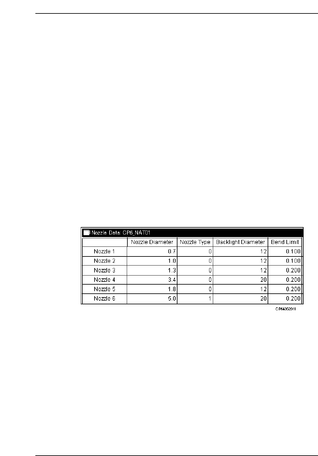
1. Start the GUE (Graphical Editor).
2. Open the “Nozzle Data” in the relevant program.
The nozzle size, the reflective disk diameter, the nozzle bend tolerance and the nozzle
type are set for each of the 1 ~ 6 nozzles. It is necessary for the actual nozzles installed in
the holders to be the same size as those specified here.
Caution: Measurement is in mm for everything except "Nozzle_type". For "Nozzle_type", enter 0
for regular nozzles and 1 for black nozzles. Use black nozzles for placing J-lead type
parts such as PLCCs and SOJs which are inspected using frontlight processing. When
"Nozzle_size"or "Back_light_size" are set to 0, that nozzle is skipped on all the holders.
Part 2 Chapter 1 Basic Operation
Edition 1.1 2-1-27 CP643E System Reference