CP643 系统参考.pdf - 第120页
1.12.9 Mark Acquisition Overlap Mark acquisition operation specifications The mark vision processing time is utilized for moving the XY-table to the next mark read position during vision processing. For example, if four …

1.12.8 D-axis Positioning When Next Production Starts
The use of a new board transport mechanism provides an improved cycle time over the
conventional board transport system, but if a large movement in the device table is
required for picking parts for the next board after placement on the first board is
completed, the result will be to reduce the improvement in the cycle time.
A change in the timing of D-axis positioning when next production starts has been
implemented to reduce the lost time associated with D-axis movement. Once vision
processing for the final sequence is complete, and any recovery sequences complete, the
D-axis is positioned at the first pick-up device. For programs that include block skip
marks, pre-pick sequence processing is not carried out in the same way (positioning at
the first pick-up device). However, if there is no setting in Proper data, the D-axis
position will be positioned at the No. 1 device position. (D-axis return processing)
D-axis return conditions
• Normal vision processing result for the last sequence (ST8)
• No recovery sequences
• Number of boards to be supplied next has been determined
• Not in turnover production
• No block skip marks (Proper data setting is required to carry out D-axis return if a
block skip mark is detected.)
If the five conditions above are not satisfied, D-axis return is carried out when
production of the next board starts, just as it has been until now.
ST1 nozzle up/down / tape feed up/down upper limit check
If the ST20 head is a skipped head then just as has been the case until now, stoppers are
engaged to prevent the ST1 nozzle and tape feed cylinder from descending. Furthermore
if ST20 is not a pick-up head, since the cam axis will rotate even if D-axis return is in
progress, an upper limit check is carried out for the nozzle and tape feed cylinder at this
time as a safety measure. If the nozzle or tape feed upper limit check sensor is OFF when
the stoppers are engaged, an emergency stop occurs.
The error messages are as follows.
In the case of a nozzle upper limit error,
ST1 : Nozzle up/down error
ST1 : UP-lmt sensor OFF
In the case of a tape feed cylinder upper limit error,
Tape feed cylinder error
These upper limit checks are carried out while the D-axis is moving.
In addition when ST1 pick-up is carried out, a check is also performed to determine
whether the ST1 nozzle upper limit is OFF. The error messages are as follows.
ST1 : Nozzle up/down error
ST1 : UP-lmt sensor ON
D-axis position processing when pre-picking and automatic operation start
As has been the case until now, D-axis positioning when automatic operation starts
(including pre-picking) means that positioning at the device position to which the
sequence has been assigned is carried out even if the ST20 head is skipped.
However, until now the start of automatic operation waited until D-axis positioning was
finished. If the ST20 head is skipped, automatic operation starts without waiting for
positioning to finish since the cam axis does not stop but continues to rotate during D-
axis return just as it does.
Part 2 Chapter 1 Basic Operation
Edition 1.1 2-1-62 CP643E System Reference
1.12.9 Mark Acquisition Overlap
Mark acquisition operation specifications
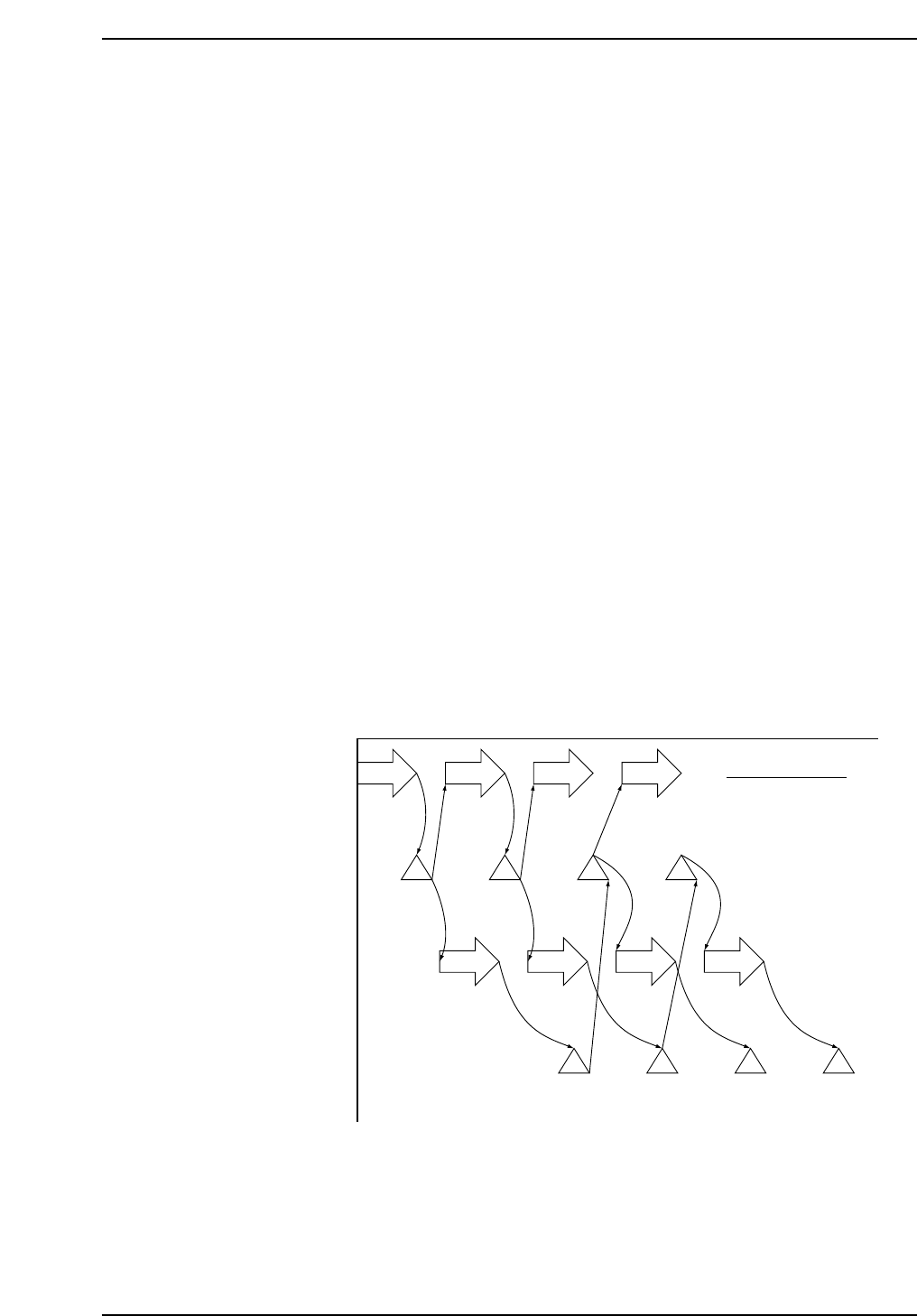
The mark vision processing time is utilized for moving the XY-table to the next mark
read position during vision processing.
For example, if four marks are to be read the operation sequence would be as follows.
[1] Movement to mark 1 position.
[2] After moving to mark 1, the mark 1 image is acquired.
[3] Mark 1 vision processing is carried out.
[3] Movement to the next mark 2 position.
[4] After moving to mark 2, the mark 2 image is acquired.
[5] Mark 2 vision processing is carried out.
[5] Movement to the next mark 3 position.
[6] After moving to mark 3, the mark 1 vision processing result is received.
[7] Mark 3 image is acquired.
[8] Mark 3 vision processing is carried out.
[8] Movement to the next mark 4 position.
[9] After moving to mark 4, the mark 2 vision processing result is received.
[10] Mark 4 image is acquired.
[11] Mark 4 vision processing is carried out.
[12] Since there is no next mark, the mark 3 and 4 vision processing results are received.
However, the above mentioned overlap processing is limited to continuous fiducial/
block skip marks. When processing a fiducial mark after a global skip mark or block
skip mark, determination as to whether the next mark needs to be read or not is made
after the result of the global skip mark or block skip mark is received.
In addition, for a block skip mark that references a fiducial mark, movement to the
intended position takes place after the referenced fiducial mark acquisition result is
received.
Z-axis height when reading marks
Mark acquisition and board check were carried out at the Z0 height until now but as a
result of a change in the mark camera and board check sensor installation positions,
mark acquisition is now carried out at the position defined by “Z0 - PCB thickness - 5.0
mm”.
XY-axes movement
Mark acquisition
(Image acquisition)
Vision processing
Vision processing
result received
[6]
Mark1
[9]
Mark2
[12]
Mark3
[12]
Mark4
[3]
Mark1
[5]
Mark2
[8]
Mark3
[11]
Mark4
[2]
Mark1
[4]
Mark2
[7]
Mark3
[10]
Mark4
[1]
Mark1
[3]
Mark2
[5]
Mark3
[8]
Mark4
For four marks
CP643S2036A
Part 2 Chapter 1 Basic Operation
Edition 1.1 2-1-63 CP643E System Reference

1.12.10 Board Check Conditions
When automatic operation or step operation is started, movement to the board check
position takes place and a board check is carried out under the following circumstances.
1. At restart after an emergency stop.
2. At restart after selection of the I/O check command.
3. At restart after XY-table board unclamping (excluding unclamping that takes place in
the context of a series of operations such as when a board is replaced).
4. When the power is turned on.
5. At restart after loader command selection (excluding the loading position command).
6. At restart after a change in the operation mode.
Product, Idle, Simulate
7. If the number of boards being managed by the software differs from the board check
result and the F6 key is used to temporarily quit automatic operation.
8. If an error occurs during board transport or changeover that has caused automatic
operation to be quit.
1.12.11 Placement Check Function
Using the live image display of the mark camera, an image of the placed parts can be
output to the image processing monitor and the parts placement status can be checked
visually.
Checking of placed parts is performed using the following procedure.
[1] Set the placement check function.
[2] Terminate board production.
[3] Check placed parts. (Page PCK)
[4] Continue production.
Setting the placement check function
Prior to terminating board production (before performing the final placement sequence),
select [PLT CHK STOP] (see page 150).
When desiring to cancel this setting, select one of the other production modes (see page
150).
Board production after setting the function
If the placement check functions is set, "Plmt Chk" is displayed in Status (P Mode) and
"Placement check stop processing" is displayed in the Help area. After production is
terminated, the placement check command (Page PCK) automatically becomes effective.
Part 2 Chapter 1 Basic Operation
Edition 1.1 2-1-64 CP643E System Reference