CP643 系统参考.pdf - 第219页
No. 5 Line Display of the auxiliary observation lines is carried out. These auxiliary observation lines can be displayed when seeking to base these lines on the observation points. In determining the auxiliary observatio…
No. 1 Tole
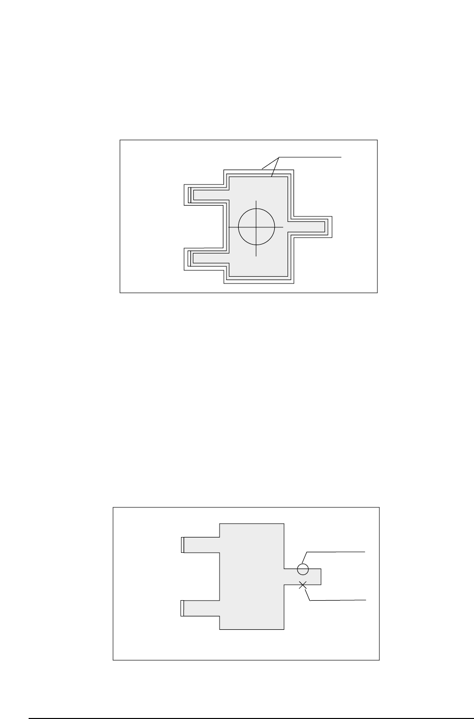
A display of the inspection results graph laid over the tolerance graph is carried out.
When either the [REINSPECT] or [ACQ INSPECT] vision command is carried out this
flag will automatically be set to ON. A graphic display of the inspection result is laid
over the tolerance information.
Tolerance Display Mode
No. 3 Point
In accordance with the algorithm, the position and size of each observation window will
display along the entire inspection distance.
No. 4 Line
Display of observation points is carried out. For example, if calipers are used, by
searching for the caliper boundaries and using the boundary points as data, the
algorithm will be able to make use of these observation points to display a graph.
If the observation point that has been found can be used as data, it will be indicated by
an [o]. If the observation point found is not suitable for use as data, it will be indicated
by an [x].
Observation Point Display Mode
Usable data
inspection point
Unusable data
CP643S3016
ID : 0001
NOZZLE : 10
X
Y
Q
: 00000
: 00000
: 00000
Tolerance limits
CP643S3015
ID : 0001
NOZZLE : 10
X
Y
Q
: 00000
: 00000
: 00000
Part 3 Chapter 3 Command Descriptions
Edition 1.0 3-3-58 CP643E System Reference

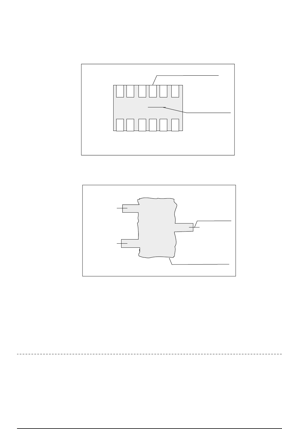
No. 5 Line
Display of the auxiliary observation lines is carried out. These auxiliary observation
lines can be displayed when seeking to base these lines on the observation points. In
determining the auxiliary observation lines the observation points that are used are
indicated by an [o] while the observation points that are not used are indicated by an [x].
In addition, the results of the angle finder and the output results of the other essential
tools are displayed for finding the blob center of gravity and the direction of inertia of
the main axis.
No. 13 Color
This is used to change the color of the graphic display to black. Normally this is not set,
in which case the display appears in white.
No. 14 Detail
All of the graphic functions are displayed along with the details of the data of each
function. In this case the trackball is necessary.
No. 15 Pause
This raises the flag when the trackball is used. When used together with other functions,
this is used for verifying the device process while the other functions such as zoom in or
zoom out are being used.
No. 24 Clp
This is used for verifying the device process for devices that use calipers. This function is
presently used for SOIC's and when the frontlight system is used, for PLCC's and
SQFP's.
No. 25 Blob
This is used for process verification when the blob function is used. This function is used
for carrying out rough device positioning. This function is presently used for SOIC's,
PLCC's, SQFP's and when the frontlight system is used.
Part 3 Chapter 3 Command Descriptions
Edition 1.0 3-3-59 CP643E System Reference
No. 26 Agf
This is used when the angle finder carries out detail verification. This function is used
when the angle or corner check is carried out during vision processing.
No. 30 AcqTime
This is used for the timing of acquisition when output is being sent to a parallel port.
No. 31 InsTime
This is used for the timing of inspection when output is being sent to a parallel port.
Revision History
V1.10 and later
Lead check OK
Boundary tracking display
CP643S3018
ID : 0001
NOZZLE : 10
X
Y
Q
: 00000
: 00000
: 00000
Blob processing display
(coarse positioning of part)
Angle finder display
(angular positioning
of part)
CP643S3017
ID : 0001
NOZZLE : 10
X
Y
Q
: 00000
: 00000
: 00000
Part 3 Chapter 3 Command Descriptions
Edition 1.0 3-3-60 CP643E System Reference