CP643 系统参考.pdf - 第123页
Placement check command The operator can enter the "Page PCK" screen outside of automatic operation by using the following command sequence. Page 000 Page 500 Page 520 Page 525 AUTO STATUS I/O PLT CHK STOP STEP…
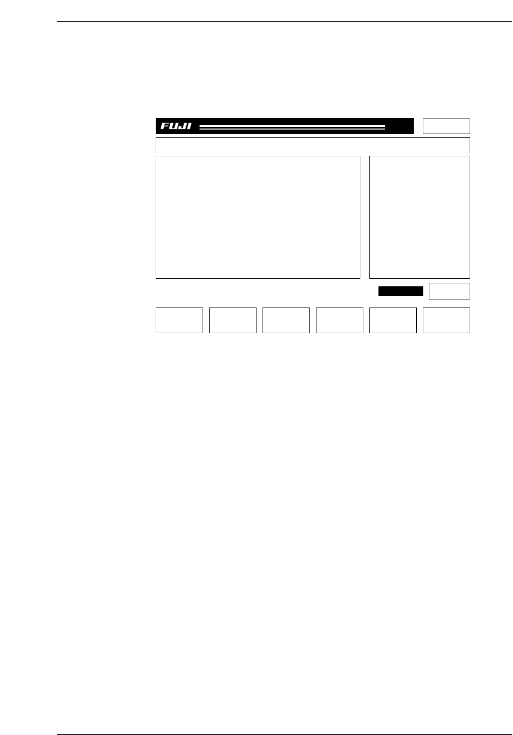
Placement check screen (Page PCK)
The "Page PCK" screen is shown below.
In the first area, information on the sequence currently displayed in the monitor is shown
(only for parts that have already been placed). Whenever any of the data are unspecified,
a "*" is displayed instead of a numerical value.
F1: GAIN/OFFSET This executes the Gain/Offset command for the mark camera. The
Proper Data values are not changed by this command. This is
effective only when in Page PCK.
F2: CAM ORG POS If pressed continuously, the cam shaft is returned to its origin
position.
F4: SEQ. NO Carries out sequence number specification.
F6: RECOVER Terminates the placement check and returns to Page 100.
START switch: This blinks if the cam shaft is at the origin position and the process
has not been completed up to the final sequence. If the START
switch is pressed, the XY table moves in the sequence order.
Resuming Production after Completing the Placement Check
When the placement check has been completed, production returns to the normal
continuous production (P Mode: Product). If the START switch is pressed, the board
was checked is unloaded, and a new board is loaded. The placement check function is
not automatically effective upon completion of board loading.
Part 2 Chapter 1 Basic Operation
Edition 1.1 2-1-65 CP643E System Reference
Page PCK
Off line
SPEC.CP6 Prod 0000 Sche 00000
V1.58
000000000000
000000000000
jog X Y C
GAIN/OFFSET CAM ORG POS SEQ. NO
CP6OA037
RETURN
PLMT CHECK
Sequence info.
Seq. No :****
X [um] :******
Y [um] :******
Q [deg] :******
D No. :***
Comment :
P mode Plmt Chk
Recovery 3 times
T mode Joint
STATUS

Placement check command
The operator can enter the "Page PCK" screen outside of automatic operation by using
the following command sequence.
Page 000 Page 500 Page 520 Page 525
AUTO STATUS I/O PLT CHK STOP
STEP MANUAL VISION
LOADER PROPER NOZZLE
PROGRAM SERVO HT
SET POSITION ETC MEMORY
* RETURN RETURN RETURN
Cautions
1. The F mark and B mark cannot be checked using this function. Only placed parts are valid.
2. In Page PCK, the mark is not reread. If the board is not clamped correctly due to Z axis
inching or abnormalities in the air pressure, coordinate deviation can occur.
3. Changes in the Gain/Offset are effective only in Page PCK. Once you exit from Page PCK,
the Gain/Offset values return to their original settings.
4. Single-board production cannot be stopped during placement check stop processing.
1.12.12 Function for Checking Board Displacement Using Fiducial
Marks
The offset value when reading the fiducial mark (the distance between the mark camera's
center and the fiducial mark) shows the amount of board displacement, and when
necessary, the machine will be stopped. This is effective in cases where parts are
mounted on the bottom surface of the boards and there is danger of interference between
the mounted parts and backup pins during production. However, it is not possible to
prevent such interference in advance.
If the machine is error-stopped, check for interference between the mounted parts and
any backup pins. A decision can then be made either to resume production or cancel
production and unload the board.
If you continue production, it is necessary to adjust the positions of the boards. Failure
to do this could result in another error stop. The permissible values for board
displacement deviation are set in the production program.
Pcb_data
Pcb_position_tolerance (0 to 12.49 mm) = 0.
The default value is 0 (the function is OFF).
Screen Display of Machine Stop Time
"Mark Check Error: Seq_no"
"Check the board's status."
"The mark correction amount exceeded the permissible value. Adjust the board
position and restart the machine, or remove the board."
Part 2 Chapter 1 Basic Operation
Edition 1.1 2-1-66 CP643E System Reference

1.13 Changing Placement Specifications Based on Part
Height
When there is a mixture of parts to be placed, some with a height of 3.0 mm or less and
some with a height over 3.0 mm, placement specifications can be changed based on
settings in Proper data in order to prevent parts that have already been placed from
interfering with parts that are to be placed (station 10).
Changes in Placement Specifications [Example 1]
The height of the parts is checked in order from the first sequence. If a sequence with a
part whose height is over 3.0 mm is detected, all the sequences before that sequence are
placed. The sequence with the part over 3.0 mm is not allocated to station 16 until all
those sequences have been placed. (At the most, stations 16 to 10 may not be allocated
with parts.)
Sequence No 1 2 3 4 5 6 7 8 9 10
-----------------------------------------------------------------------------------------------------------------
Part height in PD 1.0 1.0 1.0 1.0 3.1 3.1 3.5 3.5 4.0 4.0
In the above example all the parts up to sequence No. 4 will be placed and then the part
for sequence No. 5 will be picked.
Changes in Placement Specifications [Example 2]
Sequence No. 1 2 3 4 5 6 7 8 9 10
-----------------------------------------------------------------------------------------------------------------
Part height in PD 1.0 1.0 1.0 1.0 3.1 1.0 1.0 3.5 4.0 4.0
The same as in the first example, in example 2 all the parts up to sequence No. 4 will be
placed and then the part for sequence No. 5 will be picked. Placement is carried out
under normal specifications from sequence No. 5 onwards.
Changes in Placement Specifications [Example 3]
Sequence No. 1 2 3 4 5 6 7 8 9 10
-----------------------------------------------------------------------------------------------------------------
Part height in PD 3.1 1.0 1.0 1.0 3.1 1.0 1.0 3.5 4.0 4.0
In this case even if placement specifications are changed in Proper data, placement is
carried out under normal specifications beginning from sequence No. 1.
[Proper Data Setting]
12: Machine_Status B = XXXX XXXX XXXX XX1X (X: 0 or 1)
Part 2 Chapter 1 Basic Operation
Edition 1.1 2-1-67 CP643E System Reference