CP643 系统参考.pdf - 第217页
1. Normal Display 2. Tolerance Error Display 3. Pickup Error Display Nozzle image Expected device shape CP643S3014 ID : 0001 NOZZLE : 10 ERROR : A**** Bent lead or similar error displayed here Pitch check error displayed…
TRACE 522-2
Command Pass: [SET] - [MANUAL] - [VISION] - [TRACE]
This specifies the mode for tracing the vision processing.
Trace mode supplemental explanation
The process and results of vision processing can be viewed graphically together with the
data by setting each of the trace modes. (It is possible to combine several trace modes.)
These trace modes are used to check for problems in the device description created by
the user and through visual inspection are designed to make it as easy as possible to
grasp problems that turn up during inspection. However, due to the additional
graphical and data processing associated with the trace modes, the vision processing
speed becomes extremely slow. This function is intended for use as a debugging tool
and it should be understood that it is not normally used. If automatic operation is
carried out with the trace mode function enabled this will cause problems with
operation.
The details of these trace settings are given below.
No. 0 Result
A graphic display is carried out based on the results of inspection. When either the
[REINSPECT] or [ACQ INSPECT] vision command is carried out this flag will
automatically be set to ON.
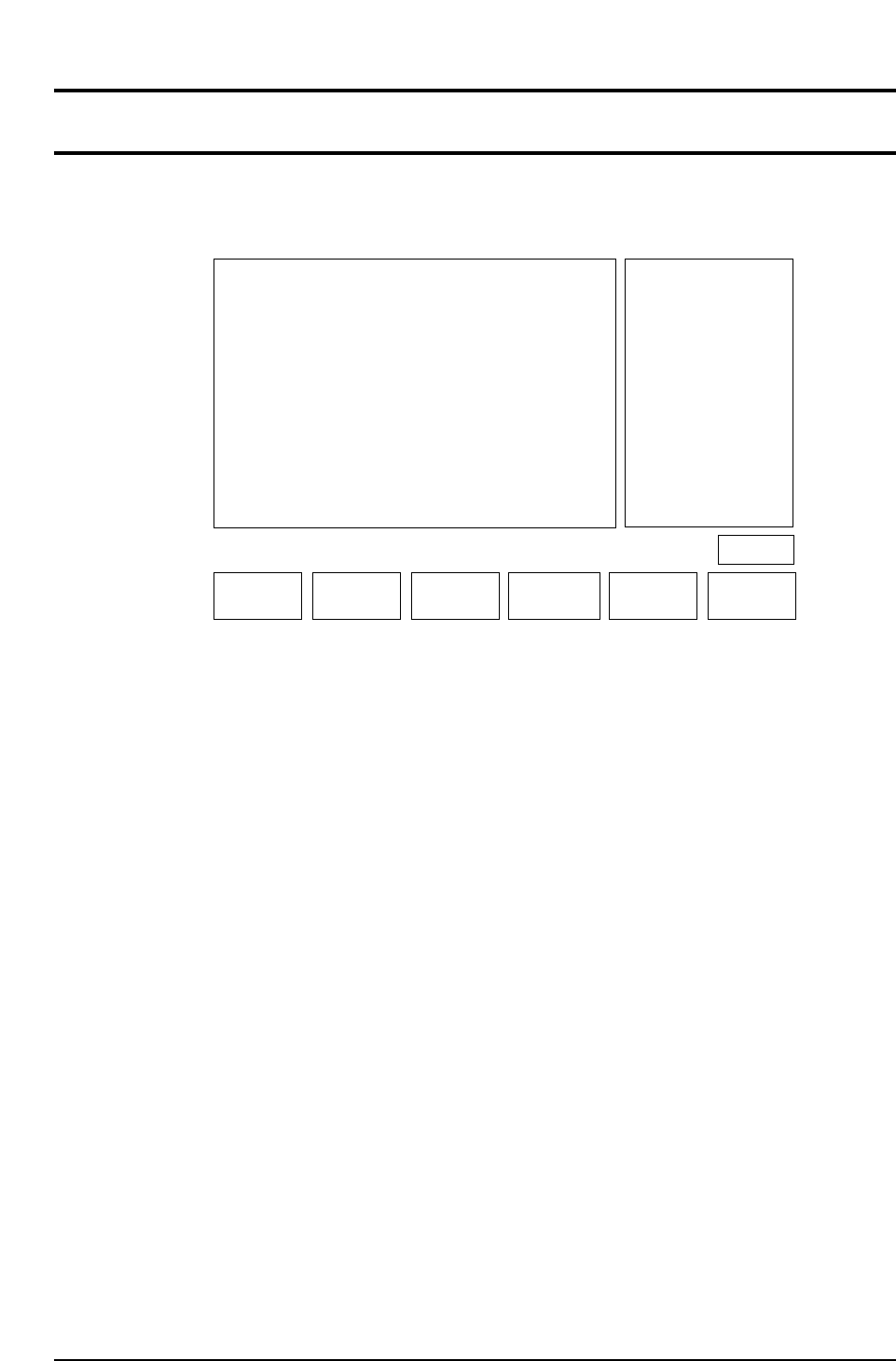
Details of the Inspection Results Graphic Display
After vision processing is complete, the recognized device center value is displayed
graphically. The amount of correction that is indicated by the outline of the device shape
and the nozzle position is then carried out. If an error has occurred the details of the
error will be displayed.
▲▼ON/OFF CLEAR
CP643S3011
RETURN
No.
0
1
2
3
4
5
6
7
8
9
10
Mode
OFF
OFF
OFF
OFF
OFF
OFF
***
***
***
***
***
Result
Tole
Window
Point
Line
RS232C
RS232C
******
******
******
******
VISION TRACE STATUS
Operation : FRONT
Ready
No.
11
12
13
14
15
16
17
18
19
20
21
Mode
***
***
OFF
OFF
OFF
OFF
OFF
OFF
OFF
OFF
***
******
******
Color
Detail
Pause
Clp
Place
Results
Timers
Inspect
******
No.
22
23
24
25
26
27
28
29
30
31
Mode
***
***
OFF
OFF
OFF
OFF
***
***
OFF
OFF
******
******
Clp
Blob
Agf
BT
******
******
Acqtime
Instime
Page 522
Select No.
Part 3 Chapter 3 Command Descriptions
Edition 1.0 3-3-56 CP643E System Reference
1. Normal Display
2. Tolerance Error Display
3. Pickup Error Display
Nozzle image
Expected device shape
CP643S3014
ID : 0001
NOZZLE : 10
ERROR :
A****
Bent lead or similar
error displayed here
Pitch check error
displayed here
Tolerance check error displayed here.
CP643S3013
ID : 0001
NOZZLE : 10
ERROR :
A****
Expected nozzle
pick-up position
Image
CP643S3012
ID : 0001
NOZZLE : 10
X : 00000
Y : 00000
Q : 00000
Straight line
connecting nozzle
center and part center
Part 3 Chapter 3 Command Descriptions
Edition 1.0 3-3-57 CP643E System Reference
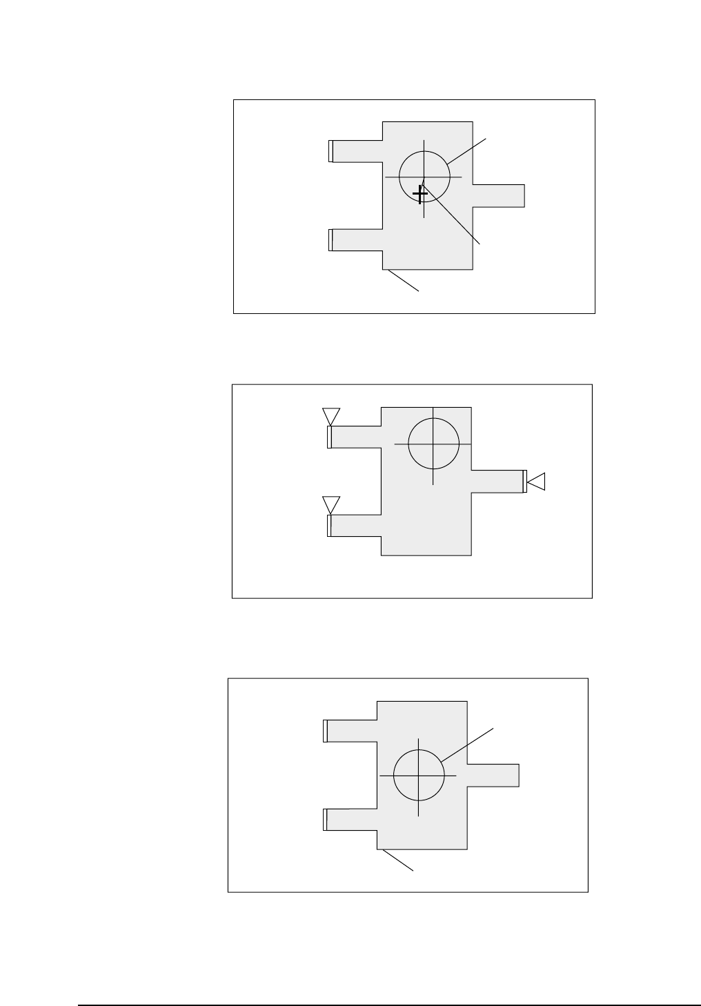
No. 1 Tole
A display of the inspection results graph laid over the tolerance graph is carried out.
When either the [REINSPECT] or [ACQ INSPECT] vision command is carried out this
flag will automatically be set to ON. A graphic display of the inspection result is laid
over the tolerance information.
Tolerance Display Mode
No. 3 Point
In accordance with the algorithm, the position and size of each observation window will
display along the entire inspection distance.
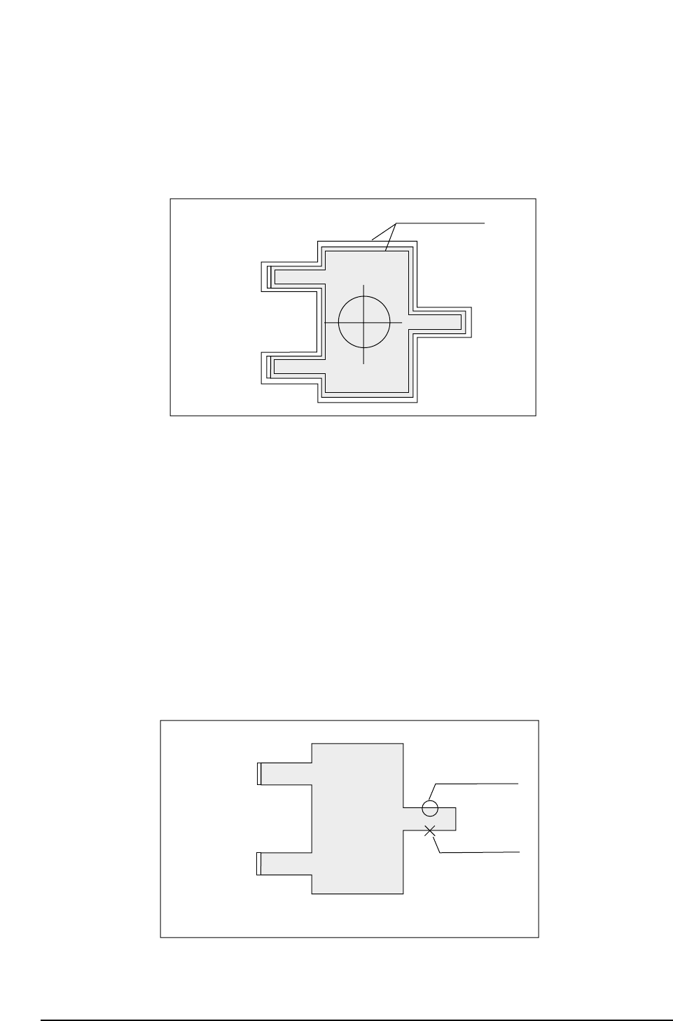
No. 4 Line
Display of observation points is carried out. For example, if calipers are used, by
searching for the caliper boundaries and using the boundary points as data, the
algorithm will be able to make use of these observation points to display a graph.
If the observation point that has been found can be used as data, it will be indicated by
an [o]. If the observation point found is not suitable for use as data, it will be indicated
by an [x].
Observation Point Display Mode
Usable data
inspection point
Unusable data
CP643S3016
ID : 0001
NOZZLE : 10
X
Y
Q
: 00000
: 00000
: 00000
Tolerance limits
CP643S3015
ID : 0001
NOZZLE : 10
X
Y
Q
: 00000
: 00000
: 00000
Part 3 Chapter 3 Command Descriptions
Edition 1.0 3-3-58 CP643E System Reference