CP643 系统参考.pdf - 第86页
(6) Setting the Reference Value for the Brightness of the Nozzle Back Light Disks It is important to maintain the reflective capacity (brightness) of the fluorescent disks attached to the nozzles in order to ensure accur…
(4) Nozzle Center Measurement Procedure
Nozzle center measurement is automatically carried out by following the command key
operation below.
[SET] – [MANUAL] – [NOZZLE] – [CENTER]
Note: For information concerning the displays of this command key operation refer to Part 3
Chapter 3, "Command Descriptions".
(5) Setting the Maximum Nozzle Bend Tolerance
When placing very small parts, the amount of nozzle bend has a major influence on
picking accuracy and the picking rate. The nozzle bend tolerance value can be set by the
user. If the results of nozzle center measurement yields a value greater than the bend
tolerance value, this allows that particular nozzle to be clearly distinguished as "NG".
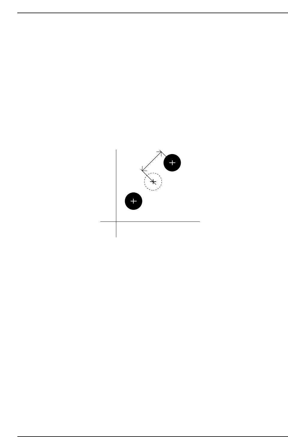
The nozzle bend amount is defined in the figure shown below.
The 2 methods for setting the nozzle bend tolerance are explained below.
Making the setting on the machine
To make the nozzle bend tolerance setting on the machine, press the following command
keys. [SET] – [MANUAL] – [NOZZLE] – [CENTER] – [TOLERANCE]
Note: For information concerning the displays of this command key operation refer to Part 3,
Chapter 3, “Command Descriptions".
Making the setting on the Host computer
<For MCS>
Specify at the “Bend_Limit” item in the NAT data.
<For F4G>
Specify at the “Bend Limit” item in the Nozzle Data.
Amount of
allowable bend
Position of nozzle tip
Conceptual nozzle origin
(nozzle center of rotation)
Nozzle tip position after
rotation of 180°
Camera center
CP643S2012
Part 2 Chapter 1 Basic Operation
Edition 1.1 2-1-28 CP643E System Reference

(6) Setting the Reference Value for the Brightness of the Nozzle Back Light Disks
It is important to maintain the reflective capacity (brightness) of the fluorescent disks
attached to the nozzles in order to ensure accurate vision processing and placement of
parts. The reference values (reference gray value, reference gray value tolerance range
and the set reference deviation tolerance range) for measuring the acceptability of the
brightness of the light given from these disks can be specified by the user. The user is
notified at the machine if the specified tolerance values are exceeded.
Reference gray scale settings
Set the following Proper data item.
547. Back light stn. Value Wide [0 ~ 255] = 170 (Default)
548 Back light stn. Value Narrow [0 ~ 255] = 150 (Default)
The settings return to the default values after a reset-start has been carried out.
Reference gray value tolerance range and set reference deviation tolerance range
settings
These values are set using commands at the machine. Select the following command
sequence to carry out these settings:
[SET] – [MANUAL] – [NOZZLE] – [CENTER] – [TOLERANCE]
Note: For information concerning the displays of this command key operation refer to Part 3
Chapter 3, "Command Descriptions”.
The tolerance range does not need to be set by the user. When a reset-start or changes to
the reference gray scale value are made in Proper data, the tolerance range is set
automatically such that measured brightness values do not exceed the tolerance range.
The brightness measure results are checked against the user’s tolerance settings if the
tolerance is set using the command sequence above.
Part 2 Chapter 1 Basic Operation
Edition 1.1 2-1-29 CP643E System Reference
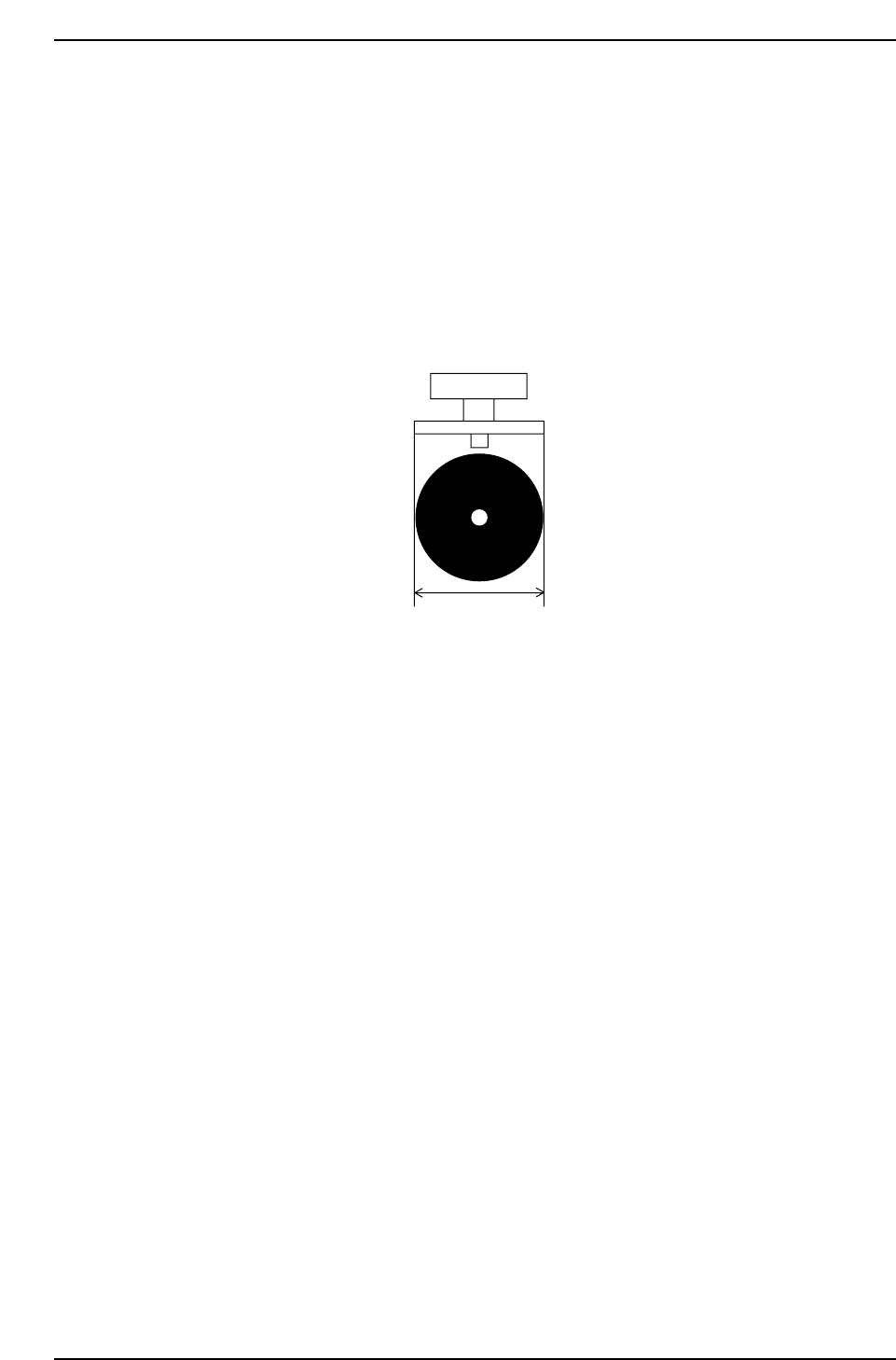
(7) Setting the Nozzle Back Light Disk Diameter
The nozzle back light disk diameter can be set which allows a wider possible range of
options related to what type of nozzle can be affixed in each holder.
Check the nozzle assignment table (under (3)”Necessary Data” in 1.4.2 “Nozzle Center
Measurement” of this chapter) for the settings.
<For MCS>
Specify at the “Back_light_size” item in the NAT data.
<For F4G>
Specify at the “Back Light Diameter” item in the Nozzle Data.
Back_light_size
CP643S2013
Part 2 Chapter 1 Basic Operation
Edition 1.1 2-1-30 CP643E System Reference