CP643 系统参考.pdf - 第231页
CENTER 523-1-0 Command Pass: [SET] - [MANUAL] - [NOZZLE] - [CENTER] The center of each nozzle is measured. The measurement results are displayed on the CRT. Note that center measurement is not carried out for black nozzl…

VP. EXE. 522-4-3-5
Command Pass: [SET] - [MANUAL] - [VISION] - [VISION TEST] - [B MARK] - [VP. EXE.]
This command can be used to execute vision processing after the image of the block skip mark for
the specified sequence has been acquired.
Note:
1. If F1 [SET DATA] has not been executed this command cannot be executed.
2. If a board is not set on the XY-table a vision processing error will result.
Processing after START is pressed
After the interference check the XY-table moves to the point on the board above the mark specified
in the sequence. Once movement is completed the mark camera light comes on and the mark image
is acquired. Vision processing is carried out after the image is acquired.
Revision History
V1.10 and later
Part 3 Chapter 3 Command Descriptions
Edition 1.0 3-3-70 CP643E System Reference
CENTER 523-1-0
Command Pass: [SET] - [MANUAL] - [NOZZLE] - [CENTER]
The center of each nozzle is measured. The measurement results are displayed on the CRT.
Note that center measurement is not carried out for black nozzles.
Note: If the vision processing version is earlier than V2.60 then messages such as “Unsuitable vision
processing version” or “Backlight check not performed” will display in yellow in the first display area for
four seconds. This simply means that the brightness measurement is not carried out during center
measurement. This is not an error status.
The display characters have the following meaning.
* (yellow) : The first center measurement has been completed.
0 (yellow) : The center measurement has been completed and is normal.
0 (yellow) : There is a possibility that a vision processing error will
occur if this nozzle is used in production.
O (purple) : Gray scale standard deviation alarm.
X (red) : A nozzle error has occurred (vision processing error).
X (red) : The nozzle diameter is outside of the limits set.
X (red) : The nozzle bend is outside of the limits set.
--(white) : Nozzle measurement has not yet finished.
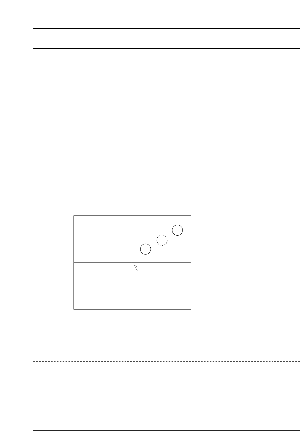
If the position of the nozzle center is as shown in the above figure, there is the possibility
depending on the size of the part, that the acquired image of the part will not fit on the screen.
Revision History
CP643S3021
Center of image acquation
Center of rotation
Second nozzle measurement position
First nozzle measurement position
Part 3 Chapter 3 Command Descriptions
Edition 1.0 3-3-71 CP643E System Reference

TOLERANCE 523-1-1
Command Pass: [SET] - [MANUAL] - [NOZZLE] - [CENTER] - [TOLERANCE]
Press to set the nozzle bend tolerance and the nozzle back light brightness reference.
Revision History
BEND LIMIT 523-1-1-1
Command Pass: [SET] - [MANUAL] - [NOZZLE] - [CENTER] - [TOLERANCE] - [BEND LIMIT]
Set the nozzle bend tolerance.
Normally, if a small tolerance is input for a nozzle which is picking a small part, the check is quite
severe.
Enter bend tolerance values in units of 1/1000 mm using the numerical keypad.
[Example] If you want to enter a value of 0.3 mm, then enter 300 using the keypad and press the CR
key.
Note: If 0 is entered the tolerance will refer to the default value of 200 (0.2 mm).
Revision History
▲ 523-1-1-1-1
Command Pass: [SET] - [MANUAL] - [NOZZLE] - [CENTER] - [TOLERANCE] - [BEND LIMIT] - [▲]
Press to move the cursor up one line. Once the cursor has reached the top, if pressed again it will
move to the very bottom.
Revision History
Part 3 Chapter 3 Command Descriptions
Edition 1.0 3-3-72 CP643E System Reference