CP643 系统参考.pdf - 第63页
(5) Parts of the Board Loader System The CP-643E sequencer loader differs from the “conveyor to conveyor” flow of the standard sequencer loader. On the CP-643E the flow is on a “receive and transfer” basis using carriers…

• STN 12: Reverse Fθ (Fine Reverse Theta)
The theta rotation angle that was performed at ST 10 is reversed. (If there
was no Pθ rotation at ST 3, at this point, the nozzle is returned to the original
position.)
Nozzle origin search is performed for all nozzle clutches when automatic
operation begins after the power is turned on, or after an emergency stop or
other alarms. (Nozzle Origin Search Sensor: Refer to Part 2, Chapter 1, 1.4.7
“Nozzle Origin Search Sensor”.)
• STN 13: Reverse Pθ (Pre Reverse Theta)
The theta rotation angle that was performed at ST 3 is reversed (At this point,
the nozzle has returned to the original position).
• STN 14: Head A detection
Head A detection is performed.
• STN 15: Confirm Nozzle Clutch Origin Position
At this station the origin position of the head is confirmed. Heads that are
not at the origin position will be skipped and returned to the origin position
next revolution at station 12.
• STN 16: Reject Parts
Parts deemed defective by the vision system and/or outside dimensional
tolerances are dumped at this station.
• STN 17: Detect Nozzle Type
Detects the selected nozzle type (No.1 to No.6) prior to nozzle changes.
• STN 18: Nozzle Change
The nozzle that will be used for the next part pick-up is selected.
• STN 19: Nozzle Change Check
Verifies that the correct nozzle is being used following a nozzle change. If
nozzle change error occurs, the erroneous head will be stopped at this
position.
• STN 20: No Function
Part 2 Chapter 1 Basic Operation
Edition 1.1 2-1-5 CP643E System Reference
(5) Parts of the Board Loader System
The CP-643E sequencer loader differs from the “conveyor to conveyor” flow of the
standard sequencer loader. On the CP-643E the flow is on a “receive and transfer” basis
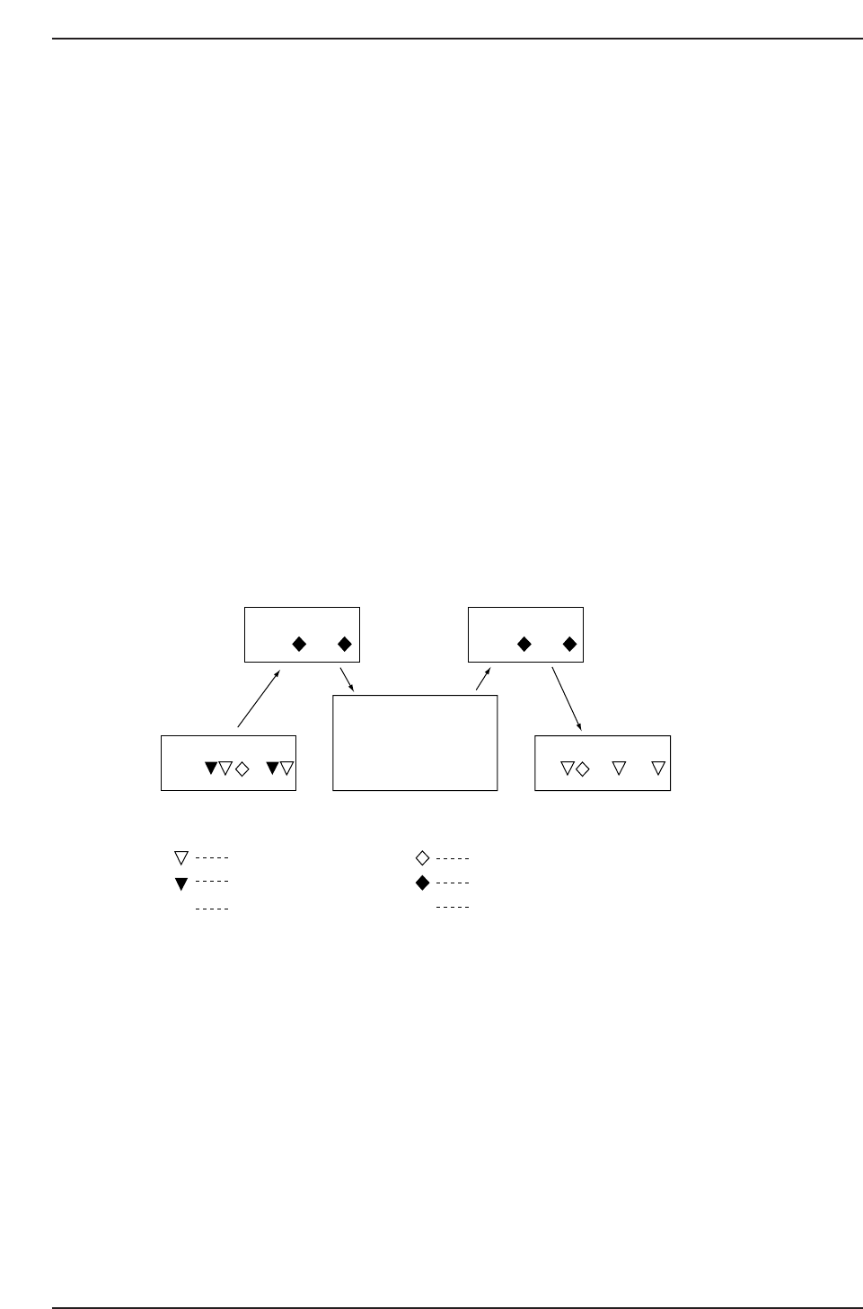
using carriers. As shown in the figure below the board loading system is divided into
three conveyors and two carriers. The direction of board transfer is as follows, from the
in-conveyor, in-carrier, main conveyor, out-carrier, to the out-conveyor. Two boards can
be simultaneously transported on each respective conveyor and carrier (For 2-board
production programs).
In-carrier: Receives boards from the in-conveyor and transfers boards to the main
conveyor.
Out-carrier: Receives boards from the main conveyor and transfers boards to the out-
conveyor.
In the case of a 2-board production program, the second board stops at the middle
stopper position on the in-conveyor thereby creating a gap between it and the first board.
The boards are transferred to the in-carrier and main conveyor in this status.
If the middle stopper position on the in-conveyor is not set correctly this will have a
negative effect on mark acquisition and part placement on the second board.
Direction of board flow →
Cautions:
1. When the main conveyor is to be unclamped, perform the unclamping operation at either
the loading or unloading position. If the XY-table is below the dropped parts tray and the
main conveyor is unclamped, there is a danger of the dropped parts tray interfering with the
clamping jaws.
2: When the in-carrier or out-carrier is advanced or retracted using an I/O operation, the
operation should be carried out with the carrier clamping jaws in the closed status.
In-conveyor
In-carrier Out-carrier
CP642S2005
M M
Main conveyor Out-conveyor
✱
✱
Board arrival sensor
Deceleration sensor
Board passed sensor
Gap check sensor
Board check sensor
Motor
M
Part 2 Chapter 1 Basic Operation
Edition 1.1 2-1-6 CP643E System Reference

1.1.3 Changing the Original Table
The original device table, the table which is used first, is selected automatically when a
new production program or table mode is selected. The conditions under which the
original table will change are listed below.
(1) Change Due to Change of Production Program
The original table is determined according to the table mode when the new production
program is selected. On-screen display content is shown in parentheses.
• Device Change Mode (2A1A) and Changeover Mode (2B1A/2A1B)
The original table changes depending on the setting in the production program as
explained below.
<For MCS>
[Program] Machine_data, 37. Original_table (Non, Table1, Table2)
Non: The table other than the table used until now is the original table. If table 1
had been used, table 2 will be the original table, and vice versa.
Table1: When the program has been changed and foreground transmission has been
carried out table 1 will be the original table.
Table2: When the program has been changed and foreground transmission has been
carried out table 2 will be the original table.
When Original_table is specified and many programs have used the same devices, then
time can be saved by not having to change feeder positions, or use commands to change
the original table.
<For F4G>
Selected at the Table_Mode section of the “CCIMF Generate” item which displays when
programs are transmitted to the machine.
• Joint Mode (JOINT)
There is no original table.
Part 2 Chapter 1 Basic Operation
Edition 1.1 2-1-7 CP643E System Reference