CP643 系统参考.pdf - 第33页
1.2.2 Operation of the Keys This section explains the keys and buttons used to operate the CP-643E series machines. (1) The Function Keys The function keys (F1 through F6) are pressed to select commands. Each function ke…
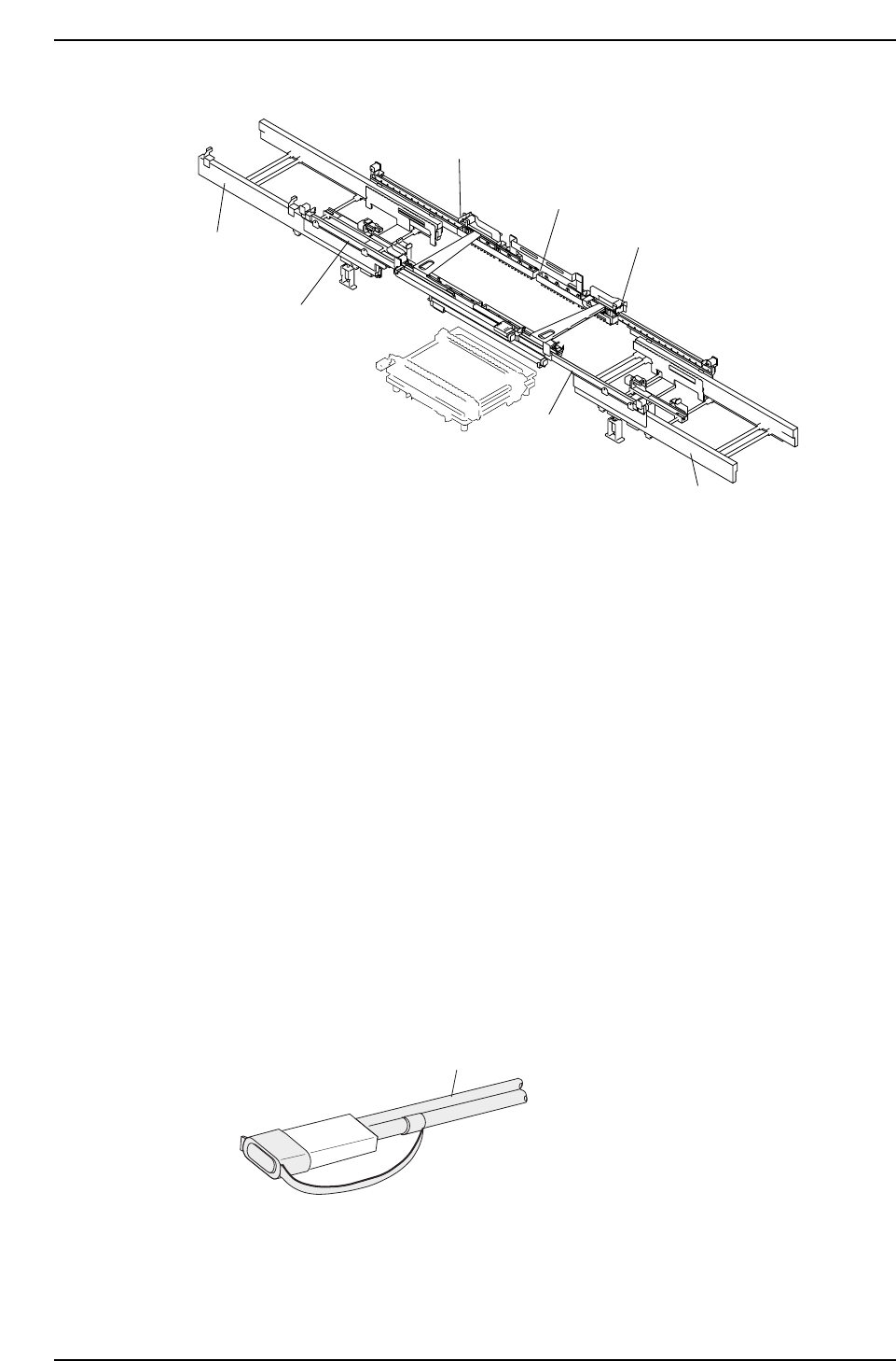
(3) Adjustable Rail Engagement Sensor
The following laser type sensor is used on the CP-643E/643ME as the main conveyor’s
adjustable rail engagement sensor.
Item name: Laser type fiber sensor
Model: FS-L71
Wavelength: 670 mm
Max. output: 3 mW
Class: 2
The following safety measures are taken:
• Laser emission indicator lamp
The amplifier is equipped with an LED lamp which indicates when a laser beam is being
emitted. The operator can see that this LED is on even when wearing protective goggles.
• Laser beam shield
A laser beam shield which can be attached to the fiber unit is supplied with FS-L series
sensors. Be sure to attach this shield when the operator must work in front of the fiber
unit where there is a risk of eye injury caused by the laser beam.
• Stopping the laser emission
Laser beam emission is stopped when the fiber unit is disconnected from the amplifier
unit.
Fiber unit
Laser beam shield attached
CP643S1005
CP643S1004
Adjustable rail engagement sensor 1
Adjustable rail engagement sensor 2
Adjustable rail engagement
sensor 3
Out-conveyor
Out-carrier
In-conveyor
In-carrier
Part 1 Chapter 1 Machine Overview
Edition 1.1 1-1-6 CP643E System Reference
1.2.2 Operation of the Keys
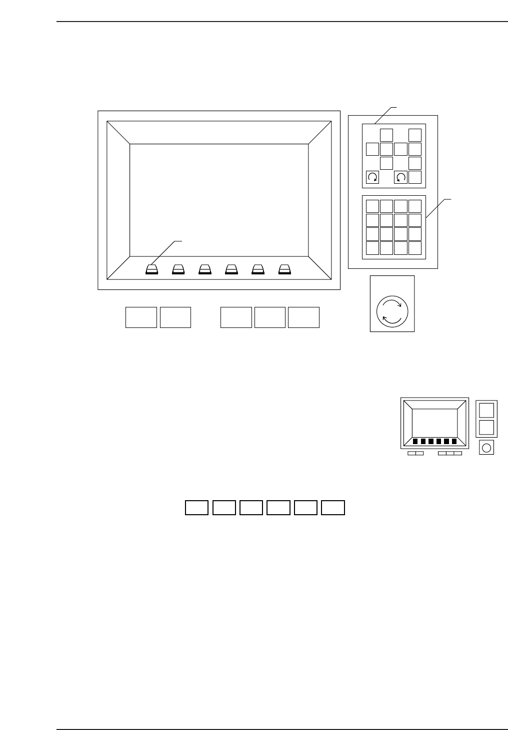
This section explains the keys and buttons used to operate the CP-643E series machines.
(1) The Function Keys
The function keys (F1 through F6) are pressed to select
commands. Each function key corresponds to a command
in the function key menu portion of the machine display.
To execute a command, press the corresponding function key.
F1 F2 F3 F4 F5 F6
CP643S1008
CP643S1007
1
2
3
4
56
7
8
9
G
#
–
F
1
2
3
4
B
S
C
R
0
↑
←
↓
→
POWER
OFF
CYCLE
STOP
POWER
ON
START RESET
Inching Keys
Numerical
Keypad
EMERGENCY
STOP
Function Keys
✽
CP643S1006
Part 1 Chapter 1 Machine Overview
Edition 1.1 1-1-7 CP643E System Reference
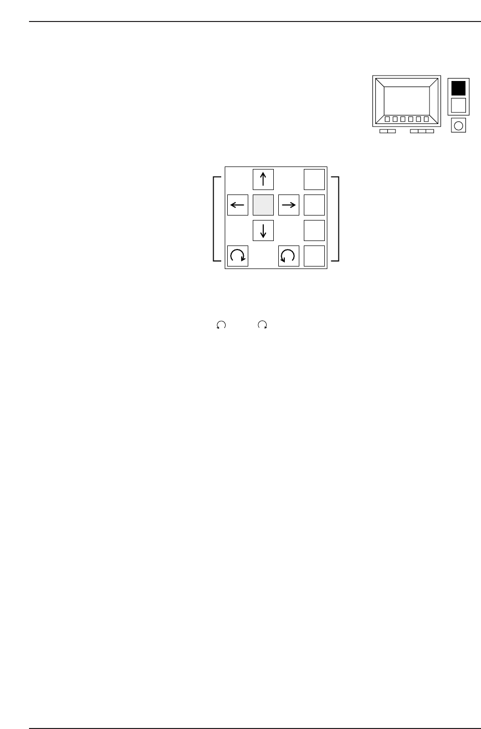
(2) Inching Keys
The “inching” function is used to move individual servo axes manually.
The inching keys are used to select the inching axes, and to
carry out inching along the selected axes.
a: Arrow keys (↑, ↓, →, ←, , and )
These keys are used to perform the inching operation. Some arrow keys are invalid
when certain inching axes are selected.
b: Inching axis selection keys (1 to 4)
These keys are used to select an axis for inching.
c: Rapid inching key (F)
Press this key and an inching key simultaneously to inch the axis rapidly.
Only those axes which are currently selected by the inching axis selection keys can be
inched.
About Inching
Inching can be carried out at any time except during machine operation or Proper data
measurement. However, it is not possible to inch all of the axes at the same time.
The axes selected by each of the inching axis selection keys and the corresponding
displays are listed below.
If the cam axis is inched when parts have been picked, those picked parts will be
discarded.
1
F 2
3
4
(a) (b)
CP643S1010
(c)
CP643S1009
Part 1 Chapter 1 Machine Overview
Edition 1.1 1-1-8 CP643E System Reference