CP643 系统参考.pdf - 第132页
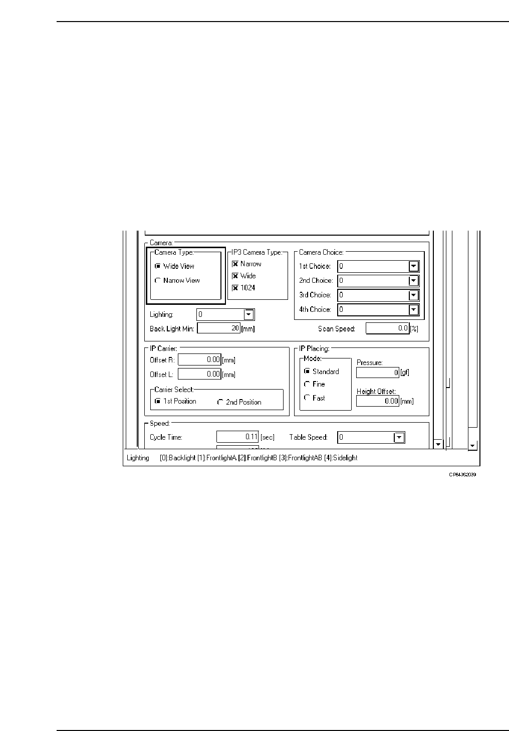
<for MCS> 12. Camera_type: Wide_view Narrow_view <For F4G> At the Environment Data’s [Camera] - [Camera Type] item, select either [Wide View] or [Narrow View]. 1. Start the VPD. 2. Open the “Part Type Data” i…

1.18.2 Wide View Camera and Narrow View Camera
(1) Wide View Camera
The wide view camera has a field of view as described below.
• Using backlighting with an S22 back light disk
The camera can handle a rectangular-shaped part with dimensions of up to 19 mm x
20 mm.
• Using frontlighting with a B22 back light disk
The camera can handle a square-shaped part with dimensions of up to 20 mm x 20
mm.
Generally speaking, the wide view camera can handle parts between size 4532 and SQFP
48 pin. It can also handle parts smaller than 4532 but with reduced placing accuracy.
(2) Narrow View Camera
The field of view for the narrow view camera is up to 9 mm x 9 mm.
This camera can handle parts from as small as 0603 to 3216.
The narrow view camera takes a small part and magnifies the picture so that high
accuracy placement can be carried out.
The narrow view camera can handle parts larger than 3216, but since it computes highly
accurate placing coordinates, vision processing on larger parts takes more time.
0603 (in. 0201) Parts Compatible Camera (Option)
It is possible to mount 0603 (in. 0201) size parts by exchanging the Narrow View Camera
for the optional camera.
Camera Specification . . . . .Narrow View Camera
Proper Data . . . . . . . . . . . . .Machine_ID:???? ???? ???? ??1?
(The ? is either a 0 or 1.) (For F4G, use "2" (decimal).)
Nozzle used . . . . . . . . . . . . .Nozzle Diameter: 0.4 mm Backlight diameter: 12 mm
Cautions with software
• Use vision software V 2.94 or a later.
• A center measurement cannot be performed using a 0.4 mm nozzle with the Wide
View Camera.
• If a 0.4 mm nozzle is specified as the No. 1 nozzle in the nozzle layout table, a program
transmission error will occur. (Error Code: 11011327).
(3) Data Necessary to Use the 2 Camera System
To make use of the 2 camera system, the following data must be entered into Proper and
Part Data.
Necessary Proper Data
137. Narrow Camera: Use
Set to “Use” when using a NARROW VIEW CAMERA.
Necessary Part Data
To use the wide camera for vision processing, set this entry in vision data to
"Wide_view", and to use the narrow camera set it to "Narrow_view." Use the NARROW
VIEW CAMERA for 3216 or smaller parts.
Part 2 Chapter 1 Basic Operation
Edition 1.1 2-1-74 CP643E System Reference
<for MCS>
12. Camera_type: Wide_view Narrow_view
<For F4G>
At the Environment Data’s [Camera] - [Camera Type] item, select either [Wide View] or
[Narrow View].
1. Start the VPD.
2. Open the “Part Type Data” in the relevant part data.
3. Click the [Environment] button to open the Environment Data, then select “CP643” at
the M/C Type item.
4. At the [Camera] - [Camera Type] item, specify whether vision processing is occur
using the WIDE VIEW CAMERA or the NARROW VIEW CAMERA.
Use the NARROW VIEW CAMERA for 3216 or smaller parts.
Part 2 Chapter 1 Basic Operation
Edition 1.1 2-1-75 CP643E System Reference

1.19 Block Skip
A single board can be divided into many smaller boards or blocks. This is called a multi-
block board. If some of the blocks on a multi-block board are defective, those blocks
must be skipped to avoid placing parts there.
1.19.1 Block Skip Method
The three methods of setting the block skip function are described below.
• Using the Skip function in N_data of program. This is effective for skipping specific
blocks in a large lot.
Note: For further information, refer to the MCS/2H System Operation Manual or F4G User’s
Manual.
• Using the [SKIP] command function on the machine.
This is effective for skipping specific blocks in a small lot.
Note: For further information refer to Section 1.19.2 (1) “Using Machine Commands” of this
chapter.
• Using the machine fiducial camera to read block skip marks. This is good for random
block skips.
Note: For more information on reading block skip marks with the fiducial camera, refer to
Section 1.19.2 (2) “Setting Automatic Block Skip Marks” of this chapter.
For further information, refer to the MCS/2H System Operation Manual or F4G User’s
Manual.
1.19.2 Setting Block Skip
The block skip can be set at the operation panel on the machine. It can also be set by
programming a block skip mark on the appropriate part of the board, which the camera
will read to determine whether a block will be skipped.
Some simple examples are described below.
(1) Using Machine Commands
1. Using the host computer Skip function in N_data, create a multi-block program and
transmit it to the machine.
Note: For further information, refer to the MCS/2H System Operation Manual or F4G User’s
Manual.
2. Select the transmitted program as the production program.
Part 2 Chapter 1 Basic Operation
Edition 1.1 2-1-76 CP643E System Reference