CP643 系统参考.pdf - 第72页
1.2.2 Zero-Setting the Machine This chapter describes the zero-setting procedure. Servo motors control the position of each of the machine’s axes. The position of these axes, however, are lost from the machine’s memory w…

13. Set the operation mode.
In either [AUTO] or [STEP], press the [MODE] command to access the following
three modes of operation.
• F1 : Product
Carries out normal production of boards.
• F2 : Simulate
The XY-table and the device tables operate as they do during production, however
boards are not loaded.
• F3 : Idle
Machine carries out all functions except vision processing and fiducial mark reading.
The loader is inoperative at this time, and boards are not exchanged.
• F4 : Idle 2
In addition to the previous “Idle” function, IN/OUT carrier operation and board transfer
operation between the XY-table and the carriers are performed. Board exchanges do not
occur.
Caution: The operation mode “Product” is automatically selected when the power supply is turned
on. Operation modes “Simulate,” “Idle” and “Idle 2” are not for assembly.
Part 2 Chapter 1 Basic Operation
Edition 1.1 2-1-14 CP643E System Reference
1.2.2 Zero-Setting the Machine
This chapter describes the zero-setting procedure.
Servo motors control the position of each of the machine’s axes. The position of these
axes, however, are lost from the machine’s memory whenever the power is turned off.
Therefore, each time the power is turned on, all axes must be returned to their servo
origin (pulse 0) positions. The procedure used to do this is known as zero-setting.
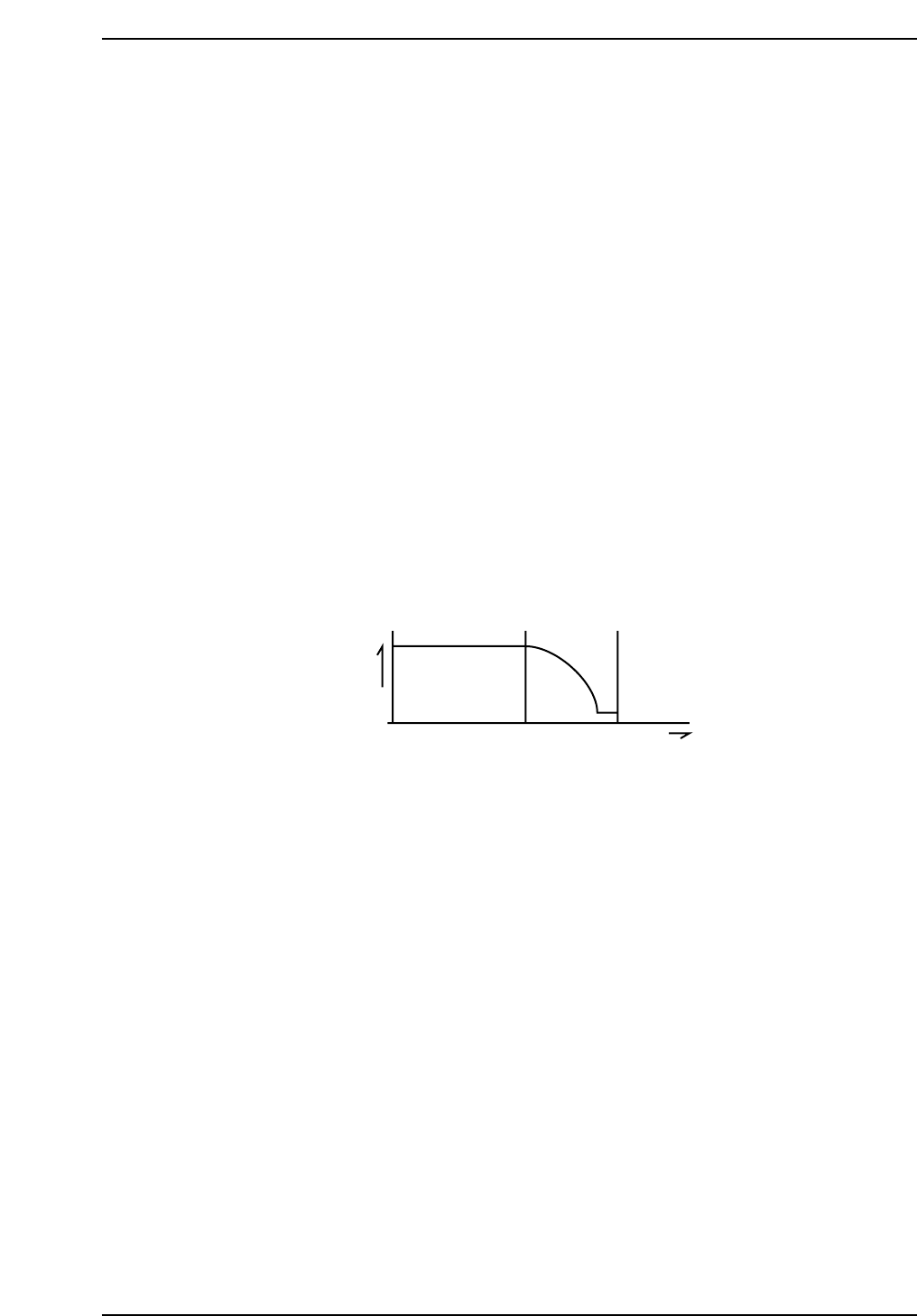
The method of zero-setting an axis is described below, using the X-axis as an example.
1. If the X-axis deceleration-point sensor input is ON, the axis initially moves in the
negative (-X) direction until this input turns OFF.
2. The X-axis moves in the positive (+X) direction and decelerates when the
X-axis deceleration-point sensor turns ON.
3. After deceleration, the X-axis inches in the positive (+X) direction.
4. The X-axis stops moving when the encoder outputs the Z signal. (The Z signal is
output only once per motor revolution.) This X-axis position becomes the zero
position.
Z signal
Speed
X-axis deceleration point
X +
CP643S2007
Part 2 Chapter 1 Basic Operation
Edition 1.1 2-1-15 CP643E System Reference

Zero-setting of all the 9 axes of the machine are performed at the same time. During
zero-setting a display like the one shown below will appear in the second display area.
After zero-setting is complete, the D1 and D2 axes tables will move to their respective
resupply positions and the shutters will then lower.
1.2.3 Shutting Down
When shutting down the power, use the following procedure.
1. Turn off the 200V power.
Press the EMERGENCY STOP button. When shutting down in the course of
production, first press the CYCLE STOP button to halt automatic operation before
pressing the EMERGENCY STOP button.
2. Turn off the main power.
Press the POWER OFF button on the operation panel to turn off the power supply.
3. Turn off the circuit breaker.
Turn off the power at the main circuit breaker if the machine is to be left unused for a
long period of time or if work is to be carried out on the servo box or control box.
Caution:
• If the power is cut while parts are being picked, the parts will drop off the nozzles, and
during the next production run, vision processing may not work properly if parts have fallen
onto the prism box. To prevent this, execute the following command sequence before
cutting the power in order to discard parts which have been picked up:
[Set] - [POSITION] - [DUMP PARTS] - [START]
• Feeder changes are not possible if the power is shut off when the device table is near the
pick-up position. Moreover, when the power is turned on again, it will take longer to zero
set the machine. Therefore, the following command sequence should be executed to move
the device table to its retract position before shutting the power off:
[SET] - [POSITION] - [D RESUPPLY] - [TABLE 1/2] - [START]
CP643S2009
Zero Set
CP643S2008
Part 2 Chapter 1 Basic Operation
Edition 1.1 2-1-16 CP643E System Reference