CP643 系统参考.pdf - 第60页
(4) Functions of Each Station The machine has twenty placing heads, labeled A to T, which rotate clockwise. Each placing head has six nozzle holders. The nozzle position is determined before part pickup. The nozzle holde…

1.1.2 Definition of Each Part of the Machine
(1) Definition of Device Tables
The CP-643E has two device (D-axis) tables, which are defined as follows:
Table 1: The right-hand device table, as viewed from the front of the machine.
Table 2: The left-hand device table, as viewed from the front of the machine.
(2) Original Table
The original table (the device table which is used first in the changeover and device
change modes) is selected automatically when a new production program or table mode
is selected.
(3) Definition of Device Numbers
The CP-643E has three device table modes. The valid device numbers in each mode are
listed below. Table mode display content is shown in parentheses.
1: Joint mode (Joint)
Two 70-device tables are synchronized and used as a 140-device table.
Valid device numbers: 1 - 140
2: Device change mode (2A1A)
One device table is used as the spare table for the other table.
Valid device numbers: 1 - 70
Caution: In this mode, the same parts must be set to the corresponding device slots of the two
tables.
3: Changeover mode (2B1A/2A1B)
Only one device table operates at any time. The other table stays at the parts supply
position to permit parts for the next production process to be mounted.
Valid device numbers: 1 - 70
Caution: Production programs specifying device numbers greater than 70 cannot be selected
in the device change mode or changeover mode. Operation is not possible if such a
program is selected.
If a device number greater than 140 is included in a production program, an error
(1101C1??/ Max D No. Error) occurs when the program is transmitted to the machine.
Part 2 Chapter 1 Basic Operation
Edition 1.1 2-1-2 CP643E System Reference
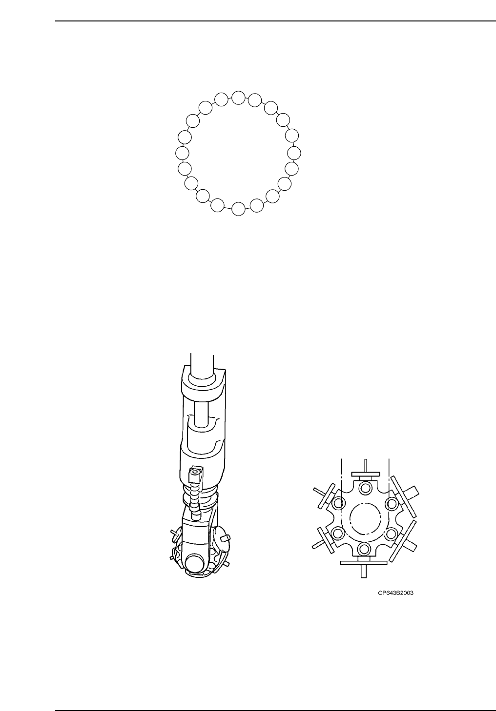
(4) Functions of Each Station
The machine has twenty placing heads, labeled A to T, which rotate clockwise.
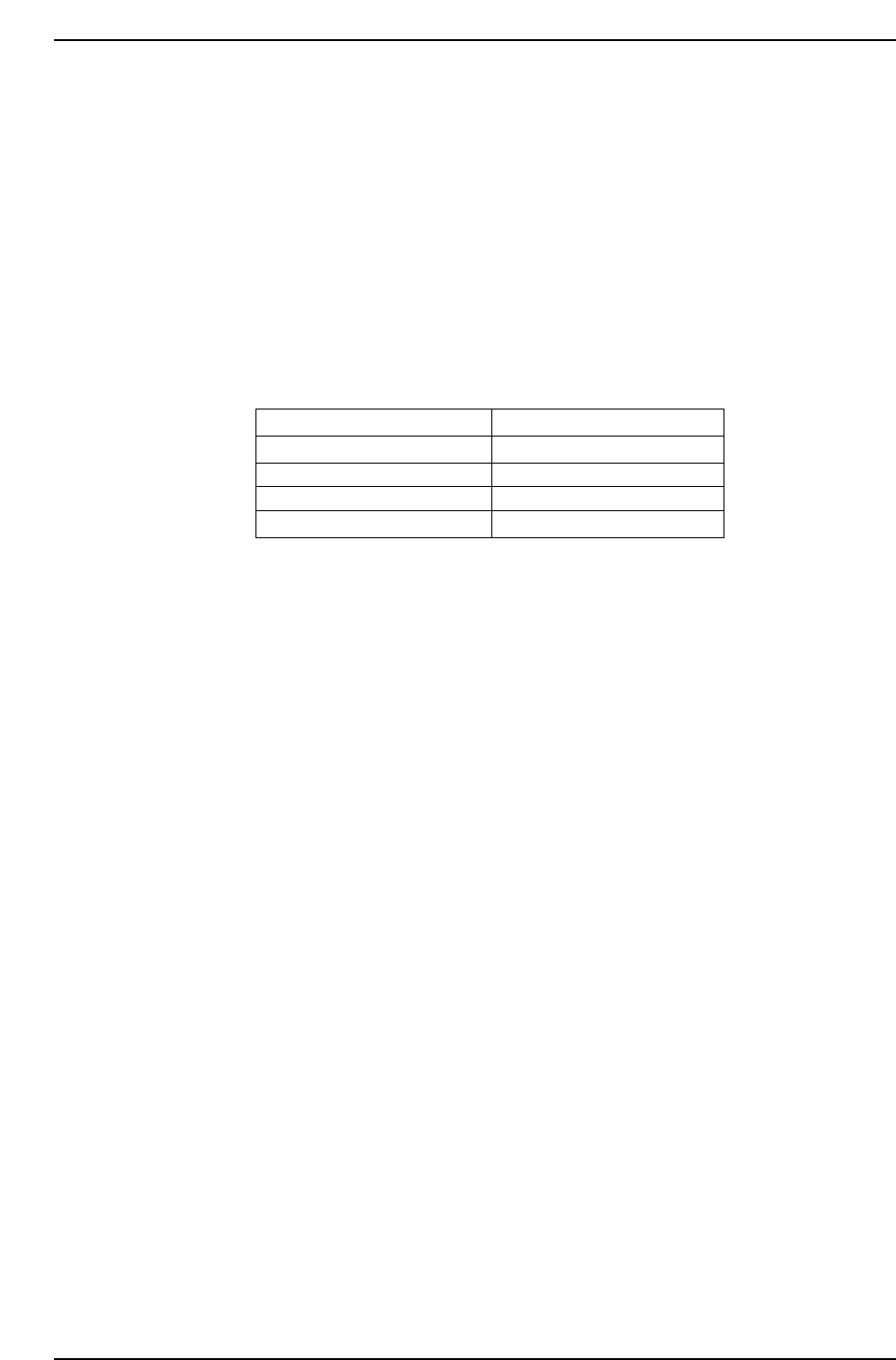
Each placing head has six nozzle holders. The nozzle position is determined before part
pickup.
The nozzle holder is shown in the following figure.
A
K
P F
G
H
I
J
L
M
N
O
Q
R
S
T
B
C
D
E
ST1
ST2
ST3
ST4
ST5
ST6
ST7
ST8
ST9
ST10
ST11
ST12
ST13
ST14
ST15
ST16
ST17
ST18
ST19
ST20
CP643S2002
Part 2 Chapter 1 Basic Operation
Edition 1.1 2-1-3 CP643E System Reference
Each index position is referred to as a “station” and the stations are labeled as ST1, ST2,
and ST3~ST20 respectively. The following roles are assigned to each station.
• STN 1: Parts Pick-up
Parts are picked from the feeder.
• STN 2: Large Parts Pick-up Check
Checks to see if a large part has been picked up.
• STN 3: Pθ (Pre Theta)
Picked up parts are rotated in 90-degree increments. Rotation angles are
shown below.
Further adjustments are made at station 10.
• STN 4: No Function
• STN 5: Nozzle θ-positioning
Nozzle clutch deviations are corrected prior to vision processing to prevent
angle deviations at ST10:Fθ.
• STN 6: The picked up part's image is acquired.
• STN 7: From the results of station 6, the corrections are computed.
• STN 8: No Function
• STN 9: No Function
• STN 10: Fθ (Fine Theta)
In conjunction with the coordinates obtained from reading the fiducial marks
on the board and using the calculations derived from the processed image at
station 6, the final adjustments of the parts rotation are made.
• STN 11: Parts Placement
The part is placed on the board using the previously obtained coordinate
data.
Rotation (Pickup --> Placing) Pθ Corrective Rotation Angle
0° ~ less than 45°
45° ~ less than 180°
180° ~ less than 315°
315° ~ 0°
0°
90°
-90°
0°
CP643S2004
Part 2 Chapter 1 Basic Operation
Edition 1.1 2-1-4 CP643E System Reference