CP643 系统参考.pdf - 第359页
5. T roubleshooting If an error occurs and the cause of which is uncertain, in order to formulate a countermeasure it is important to obtain details of the contents of the process at the time of the error. This chapter e…

11: Max Limit Position D1 and Min Limit Position D1 Check
If either of these are at 0, error code 1102233AH displays.
[Remedy]: Carry out Proper data measurement and then transmit the corrected
Proper data.
12: Max Limit Position D2 and Min Limit Position D2 Check
If either of these are at 0, error code 1102233AH displays.
[Remedy]: Carry out Proper data measurement and then transmit the corrected
Proper data.
13: Max Limit Position Z and Min Limit Position Z Check
If either of these are at 0, error code 11022331H displays.
[Remedy]: Carry out Proper data measurement and then transmit the corrected
Proper data.
14: Nozzle Place Offset X Check
If this is set at less than -2000 or more than 2000, error code 1102233CH displays.
[Remedy]: Carry out Proper data measurement and then transmit the corrected
Proper data.
15: Nozzle Place Offset Y Check
If this is set at less than -2000 or more than 2000, error code 1102233DH displays.
[Remedy]: Carry out Proper data measurement and then transmit the corrected
Proper data.
16: M/C Size Check <except CP-643>
It this is set to 5000 for the CP-6/6M/642 or 4000 for the CP-65, error code 1102233EH
displays.
[Remedy]: Carry out Proper data measurement and then transmit the corrected
Proper data.
17: M/C PCB TYPE inspection <CP-643>
The Proper data includes settings especially for 1-PCB production but if 2-PCB
production is specified in the production program, error code 1101E050H will be
returned.
[Remedy]: Set “Multiple PCB Set” to “1” in the production program.
Part 5 Chapter 4 Data Check Errors
Edition 1.0 5-4-6 CP643E System Reference

5. Troubleshooting
If an error occurs and the cause of which is uncertain, in order to formulate a countermeasure it is
important to obtain details of the contents of the process at the time of the error.
This chapter explains the special method of analysis when this type of trouble occurs.
In order to determine the cause of problems which may occur, the program counter’s trace data can
be output as described below.
Note: What is trace data?
Trace data is the equivalent of a voice recorder (black box) found on an aircraft. Simply put,
it is a chronological record of all processing which was performed by the software.
Cautions:
1. When a machine problem is detected, an emergency stop occurs and the 200V power shuts
off. The 100V power should not be turned off at such times because the trace data will be
lost if all power is shut off.
2. Print out the trace data immediately after the problem occurs and contact your Fuji
representative. The capacity of the trace data buffer is limited, and the required trace data
could be lost if other operations are performed before the trace data is printed out.
3. A one-time only print out of the S/W trace can be performed when the machine is restarted.
Please note that once this one-time printout has occurred, the data cannot be printed out
again.
Part 5 Chapter 5 Troubleshooting
Edition 1.0 5-5-1 CP643E System Reference
5.1 Trace Data Outputs (For MCS Host Systems)
Note: A printout of the trace data list requires approximately 10 sheets of printer paper.
5.1.1 When Machine Control Keys Are Operative
1. Open the door of Control Box 1 on the machine. Refer to 1.2.1 “Description of the
Machine” of Part 1 for further details.
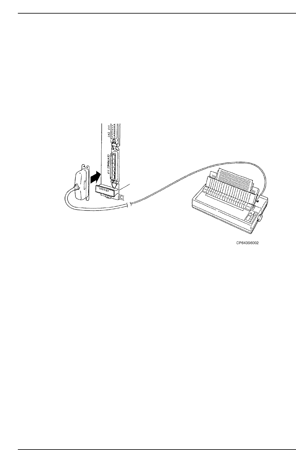
2. Find the left-most VME board, and on that board find the connector with "Printer"
next to it. Connect it with the MCS30 Printer Cable.
3. Turn the printer power ON.
4. When the CPU is running, do the following
Hold down the rapid inching key [F] and axis selection key [3]. With these keys held
down, press the axis selection key [1]. Release the keys when the printer starts.
Caution: Do not lean over the rear fence to operate the machine from the rear operation
panel. A fence alarm in the trace list will erase important command trace
information.
5. After performing the procedure above please contact Fuji.
5.1.2 When Machine Control Keys Are Inoperative
1. Perform steps 1-4 as described in section 5.1.1 above.
2. Turn the machine power off, then, with the CYCLE STOP button held down, turn the
power on again. Release the CYCLE STOP button when the printer starts.
Part 5 Chapter 5 Troubleshooting
Edition 1.0 5-5-2 CP643E System Reference