CP643 系统参考.pdf - 第80页
Insertion of Recovery Sequence If a vision processing error occurs or there are no parts and the machine is set to carry out a recovery operation, the recovery sequence will be inserted either 6 or 15 sequences later. If…

• Error Recovery Counter
Each device number is registered in the counter, and every error is registered and
sorted by device number. Each error increases the counter by one. If a part is
determined as good this counter is cleared. However, when the number of part errors
or missing parts for any given device number reaches a preset number the machine
stops.
• After a Recovery Limit Error
After the error recovery counter reaches its preset number the machine stops when the
head with the defective part reaches station 8. In this case, it is likely that sequences
for the same part have been allocated to other heads (between station 1 and 7) which
will also cause an error. To ensure the same error does not recur for part which has be
resupplied (when the machine is restarted), the error count is ignored for these parts.
• Next Device
If the error recovery counter reaches its preset number and a next device has been
specified, the next device will be used to supply parts. For detailed information
related to the next device function refer to section 1.20 “Next Device” of this chapter.
• Device Change Mode
When the error recovery counter reaches its preset number while operating in device
change mode, the other table will be used if parts have been set. For detailed
information refer to sub-section 1.3.3 “Setting the Device Table Mode” of this chapter.
• Large Parts Pick-up Check
At Station 2 the machine can check whether or not large parts have been picked. If the
results of this check indicate that a part has not been picked, the machine immediately
stops. In this case the machine stops after the first missing part is detected without
regard to the number of recovery times. Recovery is carried out when the machine is
restarted.
• Clearing the Counters After Program Change
In device change mode and joint mode, all the device number counters will be cleared.
In changeover mode, only the table which has been set as the original table will be
cleared.
Error Stop
In this mode, when parts out or an error is detected the machine will stop every time.
After the START button is pressed, a recovery operation will be carried out. Even when
operating in device change mode or when using the next device function, device change
is not carried out and the detection of an error or of parts out will halt operation.
Error Pass
In this mode, when parts out or an error is detected the machine will not stop. A
recovery operation will not be carried out. Even when operating in device change mode
or when using the next device function, device change is not carried out and operation
continues.
Part 2 Chapter 1 Basic Operation
Edition 1.1 2-1-22 CP643E System Reference

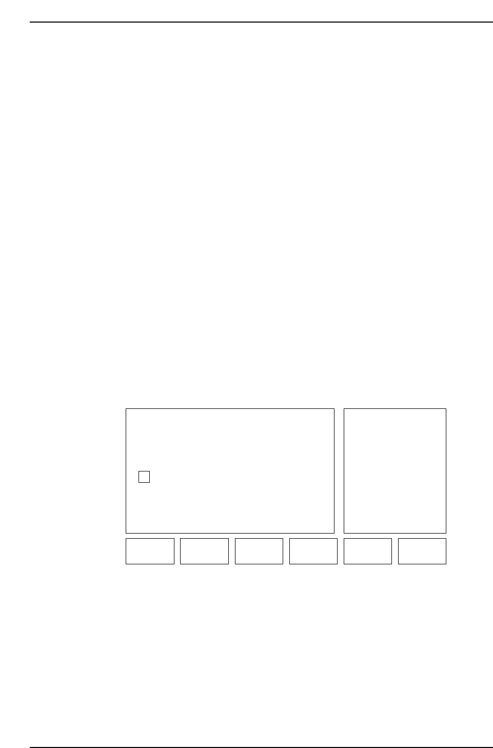
Insertion of Recovery Sequence
If a vision processing error occurs or there are no parts and the machine is set to carry
out a recovery operation, the recovery sequence will be inserted either 6 or 15 sequences
later.
If an error occurs between station 17 ~ 2 then recovery processing takes place at station 2
(this is done 6 sequences later however, this recovery processing does not include such
things as parts being discarded due to an emergency stop).
When an error occurs between station 3 ~ 10, recovery processing for such things as the
discarding of parts due to an emergency stop takes place at station 11 (15 sequences
later).
ST1
ST2
ST3
ST4
ST5
ST6
ST7
ST8
ST9
ST10
ST11
ST12
ST13
ST14
ST15
ST17
ST18
ST19
ST20
ST16
ST11: 15 sequences later
Recovery sequence
inserted at station 16
ST2: 6 sequences later
CP643S2009E
Part 2 Chapter 1 Basic Operation
Edition 1.1 2-1-23 CP643E System Reference
1.4 Nozzle Related Functions
1.4.1 Nozzle Check Function
This function checks the production program to confirm that the appropriate nozzle is
installed in each holder. This is done by performing a check on the nozzle diameter and
the back light disk size.
If a program has been transmitted to the foreground, then once program changeover has
been completed the Nozzle Check function is carried out when automatic operation
begins. If the nozzles installed in the previous production program have the same nozzle
diameter and back light disk size as the nozzles set to be used in the current production
program then no check is performed. If either the nozzle diameter or the back light disk
size are different then a check is performed. A check does not occur, for example, if a
white nozzle is replaced with a black nozzle, regardless of the nozzle size, etc.
It is necessary to set the appropriate Proper data item to enable this function. Make the
setting in the following manner:
[Proper]
136. Nozzle Check SW: This Proper data item determines whether or not the function
will be carried out.
(Example) 136. Nozzle Check SW Yes No
Yes: Mandatory nozzle check occurs
No: Mandatory nozzle check does not occur
When the Nozzle Check function is enabled a display like the one below will appear.
SET: Press this key to set the selected nozzle.
▲: Press this key to move the cursor up.
▼: Press this key to move the cursor down.
RETURN: Press this key to enter the nozzle center of rotation measurement command.
"UNSET" is displayed in red and "SET" is displayed in green.
Ready
SET ▲▼
CP643S2009A
RETURN
1
2
3
4
5
6
0.7 mm
1.0 mm
1.3 mm
2.5 mm
1.8 mm
5.0 mm
LUMI. DIAMNoz. Diam.
12 mmW
12 mmW
12 mmW
20 mmW
12 mmW
20 mmW
M/C
0.7 mm
1.0 mm
1.3 mm
3.4 mm
1.8 mm
5.0 mm
LUMI. DIAMNoz. Diam.
12 mmW
12 mmW
12 mmW
20 mmW
12 mmW
20 mmB
Program
Part 2 Chapter 1 Basic Operation
Edition 1.1 2-1-24 CP643E System Reference