CP643 系统参考.pdf - 第130页
1.18 T wo Camera System Because some parts require highly accurate placing, the vision processing system uses two cameras: a wide view and a narrow view camera. 1.18.1 Camera Mounting Position The position of cameras are…
Just as with device check and nozzle check, the START button will not be enabled if the
stopper position is not set.
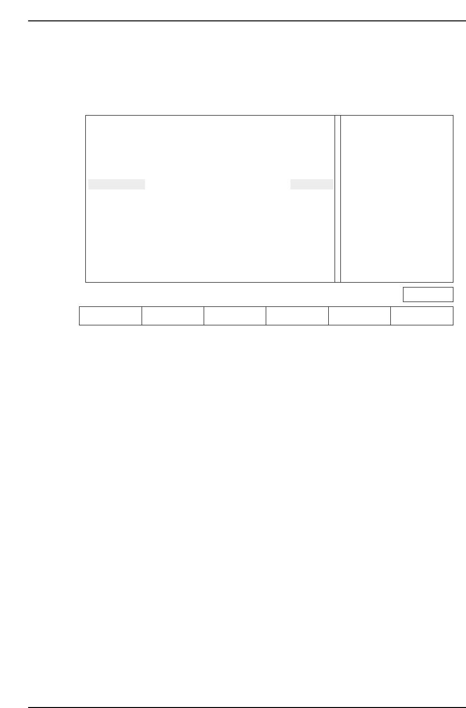
The following screen appears when the board distance check function is entered.
Action of the function keys
SET : Press this key after moving the mid-stopper position or reference pin
position to the specified position. This completes the setup.
▲ : Press to move the cursor up
▼ : Press to move the cursor down
RETURN : Press to return to the command selection screen (Page 000).
Note: The information related to the reference pin will only display if the reference pin specification
has been set in Proper data.
For reverse flow machines the display message is as follows.
“Extend IN-carrier when changing conv width
Raise main conv at IN-conv loading position”
When automatic changeover is carried out using HELPS, the above mentioned message
does not display since the conveyors are linked automatically (both standard and reverse
flow).
Check the position of the mid-stopper
Check the position of the reference pin Ready
Press [SET] to define pcb_distance
Extend OUT-carrier when changing conv width
Raise main conv at OUT-conv loading position
IN-cov
OUT-cov
Ref pin
UNSET
UNSET
UNSET
M/C
PCB_DISTANCE
-150.00 mm
-150.00 mm
-150.00 mm
PROGRAM
PCB_DISTANCE
-160.00 mm
-160.00 mm
-160.00 mm
Page 000
SET ▲▼ RETURN
CP643S2037
Part 2 Chapter 1 Basic Operation
Edition 1.1 2-1-72 CP643E System Reference
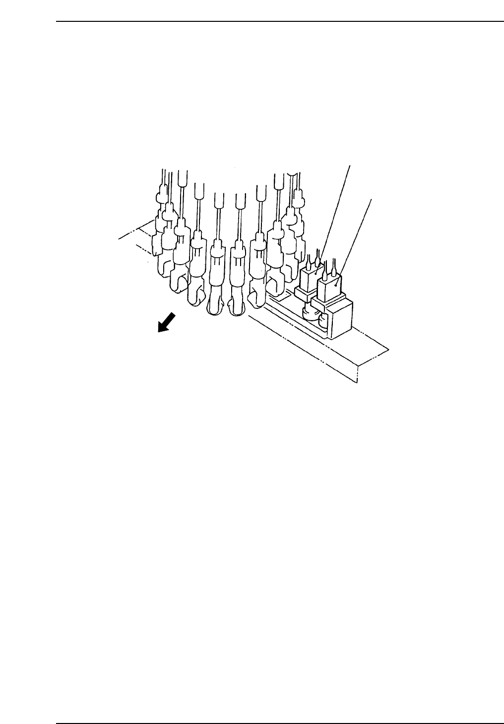
1.18 Two Camera System
Because some parts require highly accurate placing, the vision processing system uses
two cameras: a wide view and a narrow view camera.
1.18.1 Camera Mounting Position
The position of cameras are shown below.
Wide View Camera
Machine front
Narrow View Camera
CP643S2038
Part 2 Chapter 1 Basic Operation
Edition 1.1 2-1-73 CP643E System Reference

1.18.2 Wide View Camera and Narrow View Camera
(1) Wide View Camera
The wide view camera has a field of view as described below.
• Using backlighting with an S22 back light disk
The camera can handle a rectangular-shaped part with dimensions of up to 19 mm x
20 mm.
• Using frontlighting with a B22 back light disk
The camera can handle a square-shaped part with dimensions of up to 20 mm x 20
mm.
Generally speaking, the wide view camera can handle parts between size 4532 and SQFP
48 pin. It can also handle parts smaller than 4532 but with reduced placing accuracy.
(2) Narrow View Camera
The field of view for the narrow view camera is up to 9 mm x 9 mm.
This camera can handle parts from as small as 0603 to 3216.
The narrow view camera takes a small part and magnifies the picture so that high
accuracy placement can be carried out.
The narrow view camera can handle parts larger than 3216, but since it computes highly
accurate placing coordinates, vision processing on larger parts takes more time.
0603 (in. 0201) Parts Compatible Camera (Option)
It is possible to mount 0603 (in. 0201) size parts by exchanging the Narrow View Camera
for the optional camera.
Camera Specification . . . . .Narrow View Camera
Proper Data . . . . . . . . . . . . .Machine_ID:???? ???? ???? ??1?
(The ? is either a 0 or 1.) (For F4G, use "2" (decimal).)
Nozzle used . . . . . . . . . . . . .Nozzle Diameter: 0.4 mm Backlight diameter: 12 mm
Cautions with software
• Use vision software V 2.94 or a later.
• A center measurement cannot be performed using a 0.4 mm nozzle with the Wide
View Camera.
• If a 0.4 mm nozzle is specified as the No. 1 nozzle in the nozzle layout table, a program
transmission error will occur. (Error Code: 11011327).
(3) Data Necessary to Use the 2 Camera System
To make use of the 2 camera system, the following data must be entered into Proper and
Part Data.
Necessary Proper Data
137. Narrow Camera: Use
Set to “Use” when using a NARROW VIEW CAMERA.
Necessary Part Data
To use the wide camera for vision processing, set this entry in vision data to
"Wide_view", and to use the narrow camera set it to "Narrow_view." Use the NARROW
VIEW CAMERA for 3216 or smaller parts.
Part 2 Chapter 1 Basic Operation
Edition 1.1 2-1-74 CP643E System Reference