CP643 系统参考.pdf - 第87页
(7) Setting the Nozzle Back Light Disk Diameter The nozzle back light disk diameter can be set which allows a wider possible range of options related to what type of nozzle can be affixed in each holder. Check the nozzle…

(6) Setting the Reference Value for the Brightness of the Nozzle Back Light Disks
It is important to maintain the reflective capacity (brightness) of the fluorescent disks
attached to the nozzles in order to ensure accurate vision processing and placement of
parts. The reference values (reference gray value, reference gray value tolerance range
and the set reference deviation tolerance range) for measuring the acceptability of the
brightness of the light given from these disks can be specified by the user. The user is
notified at the machine if the specified tolerance values are exceeded.
Reference gray scale settings
Set the following Proper data item.
547. Back light stn. Value Wide [0 ~ 255] = 170 (Default)
548 Back light stn. Value Narrow [0 ~ 255] = 150 (Default)
The settings return to the default values after a reset-start has been carried out.
Reference gray value tolerance range and set reference deviation tolerance range
settings
These values are set using commands at the machine. Select the following command
sequence to carry out these settings:
[SET] – [MANUAL] – [NOZZLE] – [CENTER] – [TOLERANCE]
Note: For information concerning the displays of this command key operation refer to Part 3
Chapter 3, "Command Descriptions”.
The tolerance range does not need to be set by the user. When a reset-start or changes to
the reference gray scale value are made in Proper data, the tolerance range is set
automatically such that measured brightness values do not exceed the tolerance range.
The brightness measure results are checked against the user’s tolerance settings if the
tolerance is set using the command sequence above.
Part 2 Chapter 1 Basic Operation
Edition 1.1 2-1-29 CP643E System Reference
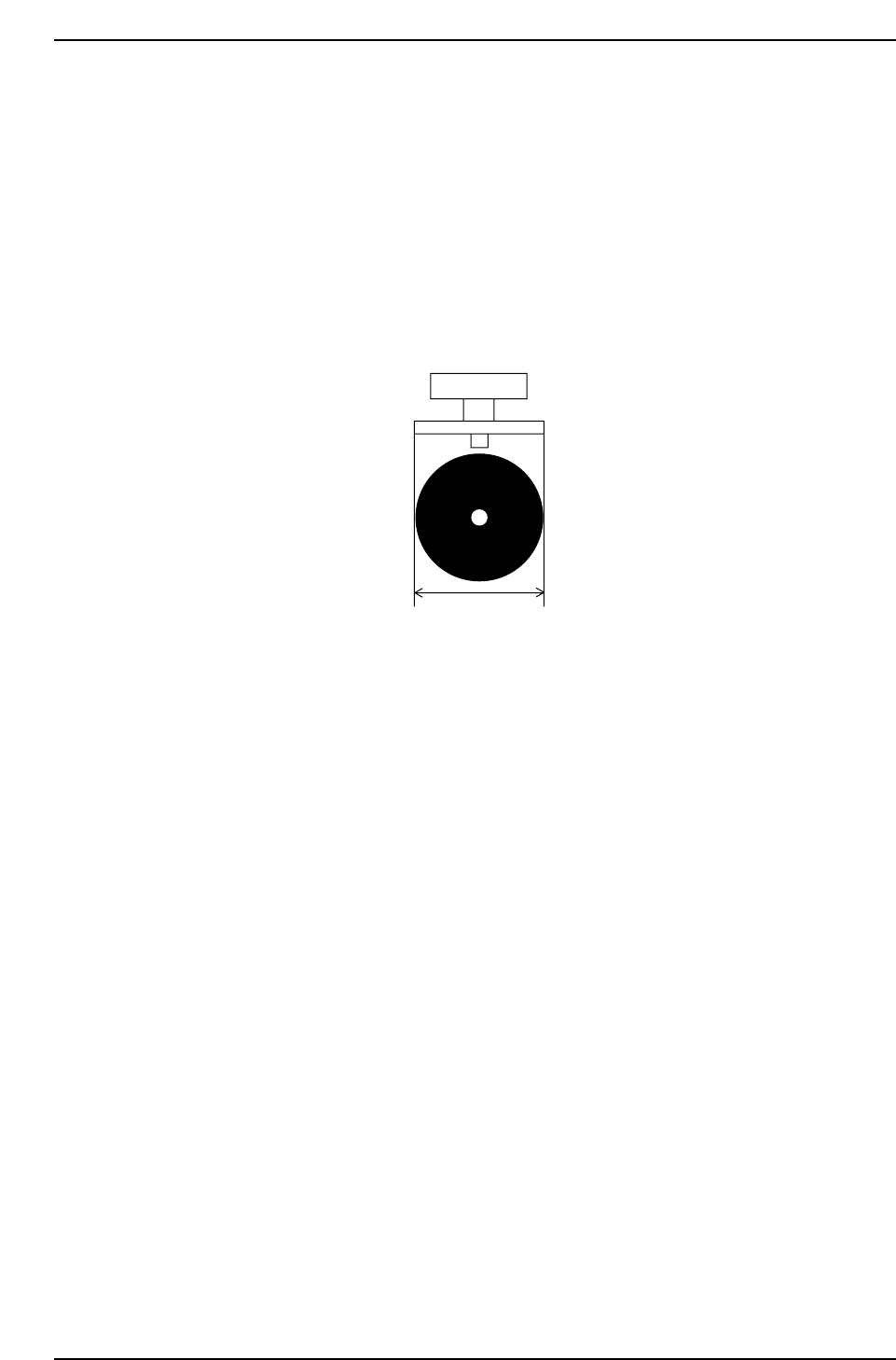
(7) Setting the Nozzle Back Light Disk Diameter
The nozzle back light disk diameter can be set which allows a wider possible range of
options related to what type of nozzle can be affixed in each holder.
Check the nozzle assignment table (under (3)”Necessary Data” in 1.4.2 “Nozzle Center
Measurement” of this chapter) for the settings.
<For MCS>
Specify at the “Back_light_size” item in the NAT data.
<For F4G>
Specify at the “Back Light Diameter” item in the Nozzle Data.
Back_light_size
CP643S2013
Part 2 Chapter 1 Basic Operation
Edition 1.1 2-1-30 CP643E System Reference

1.4.3 Automatic Nozzle Selection
The machine often changes nozzle types according to the type of board being produced.
The nozzle data used for this purpose is specified in a nozzle assignment table.
The machine selects the most appropriate nozzle for placement based on the data related
to nozzles in Part Data and on the data in the nozzle assignment table.
Data necessary for determining nozzle type
• Nozzle diameter data in the nozzle assignment table
• Nozzle back light disk size data in the nozzle assignment table
• Maximum nozzle diameter and selected nozzle diameter in Part Data
• Minimum back light disk size in Part Data
(1) Nozzle Diameter Data
The diameter of the nozzle that will be attached to each holder for carrying out
production is set in the nozzle assignment table.
Refer to 1.4.2 “Nozzle Center Measurement” of this chapter for information concerning
the procedure for specifying nozzle diameter data.
Caution: For a 0.4 mm nozzle, use nozzle Nos. 2, 3, 4, 5 or 6.
(2) Nozzle Back Light Disk Size Data
The size of the nozzle back light disk of the nozzle attached to each holder is set in the
nozzle assignment table.
Refer to 1.4.2 “Nozzle Center Measurement” of this chapter for information concerning
the procedure for specifying nozzle back light disk size data.
(3) Maximum Nozzle Diameter and Selected Nozzle Diameter
There are two fields in Part Data which are used in the automatic selection routine of the
machine. They appear under Carrying_data as follows.
PART DATA
<for MAC>
Carrying_data
17. Nozzle_size_max. : Defines the maximum diameter of the nozzle which can be used
in placing the part
Example) 17. Nozzle_size_max 1.3
36. Nozzle_size_CP6 : Defines the specific nozzle diameter when a specific nozzle size
should be used
Example) 36. Nozzle_size_CP6 1.0
Normally the optimal nozzle for placement is automatically selected from the nozzle
assignment table and the maximum nozzle size data (Nozzle_size_max).
However, if a specific nozzle is to be set, then and only then should the select nozzle size
data “Nozzle_size_CP6” be input.
Part 2 Chapter 1 Basic Operation
Edition 1.1 2-1-31 CP643E System Reference