YV180X_Ope_E.pdf - 第10页
8 EPD8013110 About this manual 2. Contents of each chapter Chapter 1 P ar t names and functions This chapter explains major part names and functions of the machine which you should know bef ore attempting operation. Chap…
7
EPD8013110
About this manual
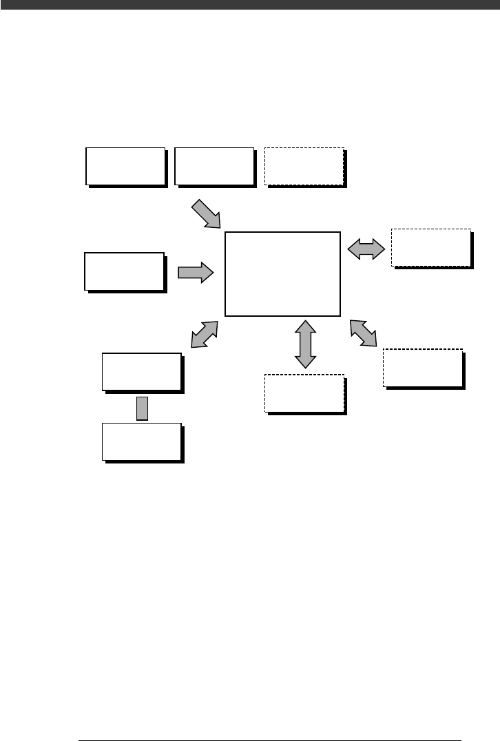
1. Structure of this manual
The illustration below shows an outline of this manual and a quick reference to
each chapter.
Quick reference to each chapter
23001D8-00
Chapter 4
Chapter 1
Chapter 2
Chapter 3
Chapter 6
Chapter 5
See service manua
l
See service manual
See "FEEDER" user's manual
Daily
operation
About VIOS
Manual
operation
Part names
& functions
Trouble-
shooting
Data creation
and editing
Useful
functions
Maintenance
Adjustment
Feeder setup
Production
evaluation

8
EPD8013110
About this manual
2. Contents of each chapter
Chapter 1 Part names and functions
This chapter explains major part names and functions of the machine which
you should know before attempting operation.
Chapter 2 About VIOS
Chapter 2 explains basic structures of the VIOS software used to operate the
YAMAHA surface mounters and also describes how to select the command
menus.
Chapter 3 Manual operation
This chapter describes how to use the joystick for manual movement of
servomotor-controlled units and other basic manual operation of conveyor
units and feeders.
Chapter 4 Daily operation
Chapter 4 describes the routine operation for PCB production, including the
conveyor unit setups.
Chapter 5 Creating the PCB data
Chapter 5 explains the basic procedures for creating or editing PCB data and
also making test-mount of components in order to check the PCB data.
Chapter 6 Using various functions
Chapter 6 explains useful functions that allow you to create or edit data more
efficiently.
Supplement
Supplement at the end of this manual gives a nozzle table showing typical
components and suitable nozzle types.
Index
Index at the end of this manual helps you quickly find where necessary items
are explained.
9
EPD8013110
About this manual
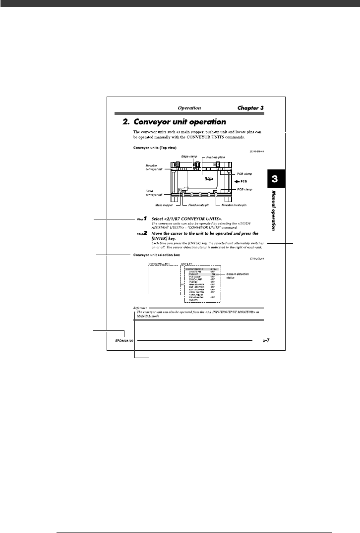
3. Page layout
The description below shows a typical page layout to help you read this
manual effectively.
Typical page layout
23002-D8-00
Step
Illustration or
table title
Note, caution or warning symbol and description
Text
Substep or
description of step
Manual No.
• Step
This describes the procedure for each operation.
• Substep or description of step
This provides detailed information on the steps in each procedure.
• Illustration or table title
This is the title of the illustration or table and appears at the upper left.
• Note, Caution or Warning
These are detailed in the “Safety and warranty” introductory section.