YV180X_Ope_E.pdf - 第222页
5 -146 EPD8013110 Operation Chapter 5 5 Creating the PCB data Refer ence T wo sets of coor dinates ar e displayed during vision cursor teaching. The left-hand coor dinates indicate the position of the upper left corner o…
5
-145
EPD8013110
Operation
Chapter 5
5
Creating the PCB data
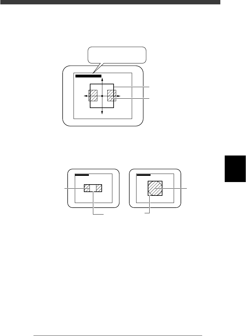
4. When you press the [TAB] once more, an asterisk (*) is prefixed to each
of the two coordinate pairs, allowing you to move the entire window
using the arrow keys.
Moving the entire window
23563-C0-00
∗(180, 170) - ∗(338, 331)
∗(180, 170) - ∗(338, 331)
Teaching windo
w
Land pattern
5. Enclose the target patterns or mark as follows.
Appropriate teaching window size
23564-C0-00
∗(180, 170) - (338, 331) ∗(180, 170) - (338, 331)
For teaching the center of patterns For teaching a mark
Pattern
Teachin
g
window
Mar
k
5
-146
EPD8013110
Operation
Chapter 5
5
Creating the PCB data
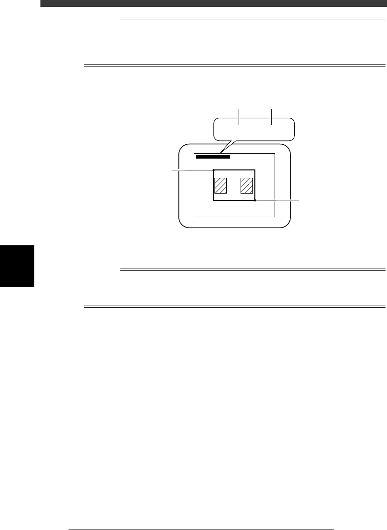
Reference
Two sets of coordinates are displayed during vision cursor teaching. The left-hand
coordinates indicate the position of the upper left corner of the teaching window, and the
right-hand coordinates indicate the position of lower right corner, both represented in
pixel units.
Teaching window position coordinates
23565-C0-00
∗(180, 170) - ∗(338, 331)
∗(180, 170) - ∗(338, 331)
B
B
A
A
5 Press the [F10] key to perform teaching.
The center coordinates of the teaching window have now been entered.
n
NOTE
Before performing vision cursor teaching, you must set teaching conditions. If you press
the [Ctrl]+[F10] keys without setting these conditions, the teaching window may not be
displayed.
5
-147
EPD8013110
Operation
Chapter 5
5
Creating the PCB data
12.3 Automatic trace
This function allows the head or camera to perform automatic trace. When
used with the mount information, the successive mount points can be
continuously traced, and when used with the component information, the
successive pickup points can be continuously traced .
1 Open the Mount Info. or Component Info. screen.
2 Set trace conditions.
See Step 1 in “12.1. Trace” in this chapter.
3 Clamp the PCB on the conveyor.
Use the <2/1/B7 CONVEYOR UNITS> utility to clamp the PCB on the
conveyor.
4 Move the cursor to the data line from which you want to
perform trace.
5 Check the surrounding area for safety.
The teaching unit will move immediately when automatic trace starts. Stay
outside of the axis movement range.
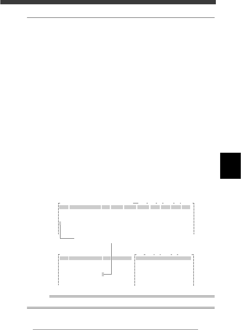
6 Press the [Ctrl] + [F9] keys to perform automatic trace.
Continuous trace proceeds until an empty line is reached. On the Mount
Info. screen, the cursor blinks in the No. column indicating which mount
point is currently traced. On the Component Information screen, the
cursor blinks in the COMMENT column indicating which pickup point is
currently traced.
Automatic trace
27567-C0-00
CAM 100% X1: 325.33 Y1: -204.13
OBJ :Mount Info.
No.
1
2
3
4
5
SignOfLandPattern
R1005
Comp
1
1
1
1
1
X
10.75
13.75
22.75
22.75
34.75
Y
8.00
9.50
11.00
8.00
8.00
R
0.00
180.00
0.00
0.00
0.00
Head
3
3
3
3
3
PCB :
FidMk
0
0
0
0
0
BadMk
0
0
0
0
0
Skip?
Exec
Exec
Exec
Exec
Exec
OBJ :Component Info.
No.
1
2
3
4
5
COMPONENT NAME
R1005
R1005
R1005
R1005
R1005
COMMENT
1.BASIC INFO.
Database No.
Comp. Package
Feeder Type
Required Nozzle
Feeder Set No.
Pos. Definition
PCB :
:
:
:
:
:
:
Tray
Fix. TF
ForQFP20mm73
Teaching
9
33
CAM 100% X1: 388.00 Y1: -204.13
Currently traced point
Mount Info. screen
Component Info. screen
n
NOTE
To interrupt automatic trace, press any key.