YV180X_Ope_E.pdf - 第142页
5 -66 EPD8013110 Operation Chapter 5 5 Creating the PCB data 4 Set the “ Feeder T ype ” parameter . Using the [INS], [DEL] or [SP ACE] key , set this parameter according to the stick feeder type you will use. • Multi-sti…

5
-65
EPD8013110
Operation
Chapter 5
5
Creating the PCB data
3.8 Setting the stick feeder component
data
When using stick feeder components (multi or single stick feeders), you
must enter the following settings in the component information.
3.8.1 When optimizing the feeder set positions
To determine the feeder set positions by data optimization (automatic
search for optimum feeder set positions), follow these steps.
1 Set the stick feeder on the feeder plate.
Install the stick feeder with components loaded on the feeder plate, at a
position that meets the following two conditions.
1. Within the working range of the moving camera
The moving camera is used for teaching of the component pickup
point.
2. On the front feeder plate
The component information is specified based on the component
supply from the front feeder plate.
Reference
For details on how to load components into a stick feeder or set a stick feeder on the
feeder plate, refer to the separate feeder user’s manual.
2 Select the component data.
Move the cursor to the data line of the component which is supplied by
the stick feeder.
3 Set the “Comp. Package” parameter in the BASIC INFO.
sub-window to “Stick”.
1. Press the [TAB] key to move the cursor into the BASIC INFO. sub-
window on the Component Info. screen. If the BASIC INFO. sub-
window is not displayed, press the [F4] key to switch the sub-window
display.
2. Align the cursor with “Comp. Package” and press the [INS], [DEL] or
[SPACE] key to set this parameter to “Stick”.

5
-66
EPD8013110
Operation
Chapter 5
5
Creating the PCB data
4 Set the “Feeder Type” parameter.
Using the [INS], [DEL] or [SPACE] key, set this parameter according to the
stick feeder type you will use.
• Multi-stick feeder
For general multi-stick feeders, set this parameter to “Multistick”. For
wide multi-stick feeders, set to “WideMultiStk”.
• Single stick feeder
Select from among “Stick 15mm, “Stick 20mm”, “Stick 25mm”, “Stick
30mm” and “Stick 35mm” according to the stick width. For other
stick feeders, select from “Stick-A” to “Stick-G”. (See the reference
below.)
• High-speed stick feeder
Select from among “HS-Stick-L06”, “HS-Stick-L09”, “HS-Stick-L13”,
“HS-Stick-L16”, “HS-Stick-L20”and “HS-Stick-L26”. (Each number
indicates the length of component.) For other high-speed stick
feeders, select from “HS-Stick-A” to “HS-Stick-D”. (See the reference
below.)
• Stacked stick feeder
Select from among “StackStk-L06”, “StackStk-L09”, “StackStk-L13”,
“StackStk-L16”, “StackStk-L20”and “StackStk-L26”. (Each number
indicates the length of component.) For other stacked stick feeders,
select from “StackStk-A” to “StackStk-D”. (See the reference below.)
Reference
When you set the Feeder Type parameter to “HS-Stick A to D” or “StackStk-A to D”, you
must first make correct settings for ”FEEDER SPEC. CMN.” of <3/1/B4 FEEDER SPEC.
INF> in the MAINTENANCE Manager. For details on settings, refer to the mounter
service manual.
5 Set the feeder set No. in the BASIC INFO. sub-window.
Enter the number of the feeder set position at which the stick feeder
knockpins are inserted into the feeder plate.
6 Set the Pos. Definition parameter.
Set this parameter to “Automatic” when not using a multi-stick feeder and
advance to Step 9. When using a multi-stick feeder, proceed to Step 7.
7 Move the teaching unit to the feeder set position by trace.
1. Set the Pos. Definition parameter to “Automatic”.
The coordinate of the feeder set position specified in Step 5 is auto-
matically entered in the Feeder Pos_X column.
2. Press the [TAB] key to return the cursor back to the main window.
Check that the cursor is positioned on the data line you are editing.
3. Press the [F9] key to perform trace.
The teaching unit moves to the position specified in the Feeder Pos_X
column. The trace (teaching) conditions should be set as follows.
Teaching unit : Select “camera”
Speed : Select a slow speed (SPEED=20 to 40).
Fiducial : Select “NotUse”.
5
-67
EPD8013110
Operation
Chapter 5
5
Creating the PCB data
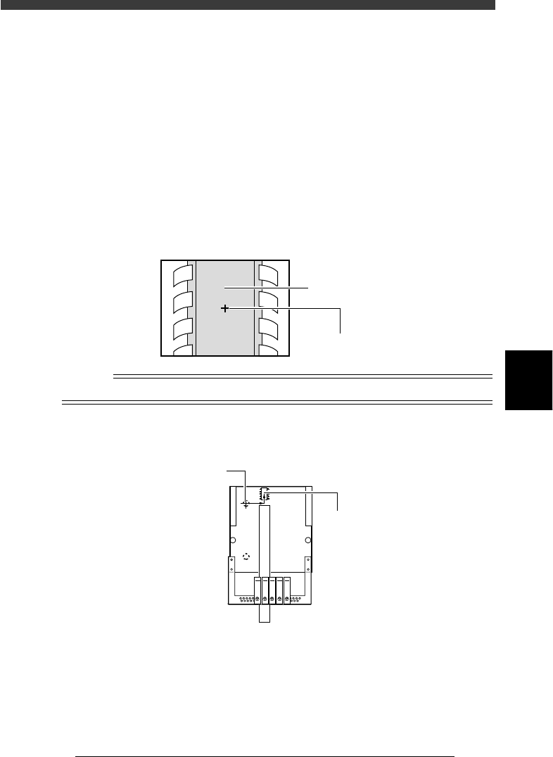
8 Perform teaching for the pickup position.
Referring to the procedure below, perform teaching for the coordinates of
the component pickup position.
1. Press the [TAB] key to move the cursor back to the BASIC INFO. sub-
window.
2. Change the Pos. Definition parameter to “Relative”.
3. Move the cursor to “Feeder Pos_X mm”.
4. Manipulate the YPU joystick to move the camera directly above the
component to be picked up.
Making sure that the cross cursor is positioned at the center of the
component, press the [F10] key twice to perform teaching. The
teaching position coordinates relative to the feeder knockpin have now
been entered.
Teaching position
23525-C0-00
Component
Cross cursor
(Teaching position)
Reference
Marking at the center of the component with a pencil makes it easier to perform teaching.
Teaching position coordinates
23526-C0-00
X
Y
Feeder
positioning
knockpin
Pickup poin
tPickup point
Pickup poin
t