YV180X_Ope_E.pdf - 第204页
5 -128 EPD8013110 Operation Chapter 5 5 Creating the PCB data 10.3.3 Component pickup err or If components cannot be picked up from the ta pe feeder , or components are picked up at an incorrect position (picked up on th…
5
-127
EPD8013110
Operation
Chapter 5
5
Creating the PCB data
3 Check the parameters and correct them.
If the same error occurs even after you have performed vision cursor teaching,
the Mark Info. settings are probably incorrect. Check the Mark Info. parameters
and correct them.
1. Select <1/2/PRD DATA>→”Mark Info.” and press the [ENTER] key.
The Mark Info. screen then appears.
2. Line up the cursor with the target mark data line and check its parameter
settings (such as “Mark Type”, “Mark OutSize”, “Shape Type” and “Surface
Type” while switching the right-hand sub-windows with the [F4] key.
Correct these parameter settings as necessary.
3. Press the [F6] to run the Adjust Assistant and check or adjust so that the
mark is recognized correctly.
4. Press the [ESC] key and run the <1/2/C7 UPDATE VISION DATA> com-
mand to update the data.
5. Select the <1/2/C0 SAVE & EXIT> command to save the data.
4 Resume the automatic operation.
Run the <1/1/A2 AUTO RUNNING> command to resume the automatic
operation.
Reference
For detailed information on the Mark Info. parameter settings and the Adjust Assistant
commands, refer to “4. Creating the mark information” in this chapter.

5
-128
EPD8013110
Operation
Chapter 5
5
Creating the PCB data
10.3.3 Component pickup error
If components cannot be picked up from the tape feeder, or components are
picked up at an incorrect position (picked up on the side, slantly or at a
position off the center), inspect how the nozzle reaches a component. To do
this, press the [Space] bar to temporarily stop the machine at the instant the
nozzle picks up a component and check to see if it reaches the component.
As an alternative, set the operating speed to 10% or less by using the YPU
[SPEED] key to observe the nozzle movement over the feeder. In particu-
lar, check and correct the following points.
Check point 1: Component feed
Check if the nozzle tip center matches the center of a component on the
feeder when the nozzle picks up the component.
If not, check the feed pitch and movement of the feeder. For details on
feeder adjustments, refer to the separate feeder operation manual.
n
NOTE
The teaching and trace functions help you check and correct the pickup point. Refer to
“12. Teaching and trace” and “8.1 Checking the component information” in this chapter.
Check point 2: Pickup height
Check whether the nozzle height is appropriate when the nozzle picks
up a component from the feeder.
If the nozzle presses on the component too much or does not reach the
component, correct the data as follows.
1. When the machine operation is interrupted due to an error, reset the
error and exit the RUNNING mode with the <1/1/E0 EXIT FROM
RUNNING> command.
2. Select <1/2/PRD DATA>Æ”Component Info.” and press the [EN-
TER] key. Line up the cursor with the data line of the target compo-
nent.
3. Press the [F4] key to switch the sub-window to “PICK & MOUNT
INFO.”, then enter an appropriate value in the Pick Height column.
Normally, enter 0 to -0.5 when components are fed on paper tape,
while enter 0 to 0.5 when fed on embossed tape. (See the reference
description below.)
4. When data correction is complete, press the [ESC] key and select the
<1/2/C0 SAVE & EXIT> command.
5
-129
EPD8013110
Operation
Chapter 5
5
Creating the PCB data
Reference
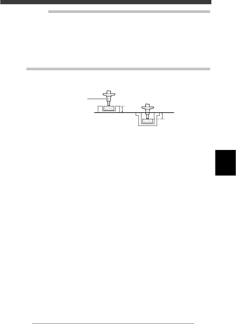
For components fed on paper tape, their surface (delivery height) is about 0.5mm higher
than the typical reference height (the nozzle tip height when the Pick Height parameter in
the PICK & MOUNT INFO. sub-window is set to 0.0mm. So, enter 0 to -0.5mm in the Pick
height parameter column. It is advisable to enter a value that allows the nozzle to press
the component by about 0.2mm. But, carefully select this value to prevent the nozzle from
pressing the component too much, otherwise the tape bottom may be broken causing the
component to stand on its side.
For components fed on embossed tape, their surface is about 0.5mm lower than the typical
reference height, so enter “0 “to “0.5mm” for the Pick height parameter.
Component delivery height
23556-C0-00
0.5mm
0.5mm
Paper tape Embossed tape
Reference height
Nozzle
Checkpoint 3: PICK & MOUNT parameters
If you found nothing wrong by visual check, try adjusting the PICK &
MOUNT INFO. parameters in the component information as explained
below.
• Pick Timer:
Set this parameter to a value slightly larger than the current setting.
• Pickup Speed:
Set this parameter to a value slightly smaller than the current setting.
When the data has been corrected, press the [ESC] key and select the
<1/2/C0 SAVE & EXIT> command.
Checkpoint 4: Feeders
If the component cannot be still picked up even after taking corrective
action according to checkpoints 1 to 3, try replacing the feeder with
another one. If no error occurs with the new feeder, the former feeder
probably has a problem. Contact the YAMAHA sales representatives in
your area.