YV180X_Ope_E.pdf - 第218页
5 -142 EPD8013110 Operation Chapter 5 5 Creating the PCB data 12.2 T eaching The teaching function is used to teach the machine a position such as XY coordinates. There are tw o teaching methods: “point teaching” and “vi…
5
-141
EPD8013110
Operation
Chapter 5
5
Creating the PCB data
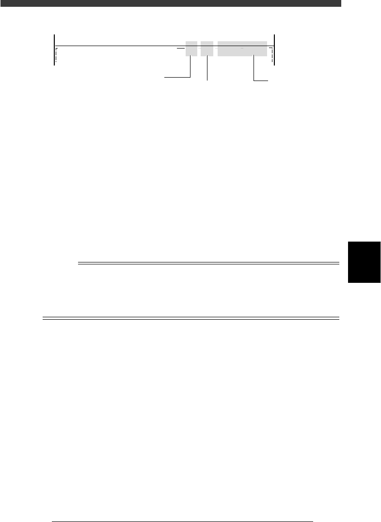
Teach/trace condition display
27566-C0-00
PCB :
<<<APPLICATION>>>
<<MODE>> 1/EDIT_DATA
2/DATA/M
CAM 100% X : 17.00 Y : 19.00
OBJ :Mount Info.
Current position
Current position of
teaching unit
Axis moving speed
Displayed in percent
Teaching unit
CAM: Camera
H1: Head 1
H8: Head 8
2 Clamp a PCB on the conveyor.
Use the <2/1/B7 CONVEYOR UNITS> utility to clamp the PCB on the
conveyor.
3 Align the cursor with the item for which you want to
perform trace.
On the Mount Info. screen, for example, move the cursor to the line of the
data to which you want to perform trace.
4 Check the surrounding area for safety.
The teaching unit will immediately move when you perform trace, so
placing any part of your body within the axis movement range can be
hazardous. Be sure to stay out of the movement range.
5 Press the [F9] key to perform trace.
The teaching unit moves to the position you specified in Step 3.
Reference
When you press the [Shift]+[F9] keys, the cursor moves down to the next data line after
performing the trace. You can also perform continuous trace by keeping the [Shift]+[F9]
keys pressed, or automatic trace by pressing the [Ctrl]+[F9] keys starting from the
selected line running towards lower lines until an empty line is reached. (See “12.3
Automatic trace” in this chapter for more details.)

5
-142
EPD8013110
Operation
Chapter 5
5
Creating the PCB data
12.2 Teaching
The teaching function is used to teach the machine a position such as XY
coordinates. There are two teaching methods: “point teaching” and “vision
cursor teaching”.
12.2.1 Point teaching
Point teaching is further divided into “single point input” and “multi-point
input”. The “single point input” allows the teaching data to be directly
entered, while the “multi-point input” gives the center coordinates in the
multiple positions which are specified. The steps below explain the teach-
ing procedure in the DATA Manager.
1 Set teaching conditions.
As with the trace function, use the <2/1/B0 TEACH, TRACE CONDITION>
command. (Refer to Step 1 in the previous section “12.1 Trace”.)
2 Secure a PCB on the conveyor.
Use the <2/1/B7 CONVEYOR UNITS> utility to secure the PCB on the
conveyor.
3 Move the cursor to the item for which you want to perform
teaching.
On the Mount Info. screen, for example, move the cursor to the line of the
data for which you want to perform teaching.
4 Move the teaching unit to the target position.
Check safety and stay out of the axis movement range, then manipulate
the YPU joystick to move the teaching unit to the target position.
5 Press the [F10] key to perform teaching as follows.
For “single point input”:
Press the [F10] key twice.
When you first press the [F10] key, a short beep sounds, then press the
[F10] key again to enter the teaching data.
For “multi-point input”:
1. At the first teaching point, press the [F10] key twice while holding
down the [Shift] key.
2. At the subsequent teaching points, press the [F10] key once per point
while holding down the [Shift] key.
3. At the last point, press the [F10] key only.
The center coordinates in the area specified by multiple teaching points
are now entered for the data at which the cursor is aligned.
4. If you want to cancel the teaching data, select <2/1/D9 ABORT PCB
DATA> and press the [ENTER] key.
Reference
Teaching can also be performed by executing the <2/1/B9 TEACHING> command. For
manipulating the YPU joystick, refer to “3. Manual operation” in Chapter 3.
5
-143
EPD8013110
Operation
Chapter 5
5
Creating the PCB data
12.2.2 Vision cursor teaching
Vision cursor teaching allows you to obtain position data which is more
accurate than normal point teaching. A teaching window with any desired
size is displayed on the vision monitor and its center position obtained. The
target mark or pattern must be displayed on the vision monitor.
1 Clamp the PCB on the conveyor and set teaching condi-
tions.
As with point teaching, clamp the PCB on the conveyor, and set teaching
conditions by executing the <2/1/B0 TEACH, TRACE CONDITION>
command. In this case, the teaching unit must be set to “Camera”.
2 Move the camera to the target position.
Check safety and stay out of the axis movement range, then manipulate
the YPU joystick to move the camera to above the target position.
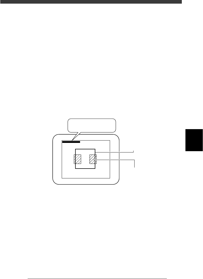
3 Press the [Ctrl] + [F10] keys.
A teaching window appears on the vision monitor as shown below.
Vision cursor teaching
23560-C0-00
∗(180, 170) - (338, 331)
∗(180, 170) - ∗(338, 331)
Teaching windo
w
Land pattern
4 Adjust the teaching window position and size to match the
pattern or mark size.
At the top left of the vision monitor, the coordinates of two diagonal
corners of the window are displayed. Adjust the window position and size
to match the pattern or mark size as follows:
1. When an asterisk (*) is prefixed to each of the two coordinates as
shown above, pressing the arrow keys allows the window to move in
the direction indicated by arrow.
Use the arrow keys to move the window so that its upper left or lower
right corner is properly positioned for the target land patterns or mark.