YV180X_Ope_E.pdf - 第157页
5 -81 EPD8013110 Operation Chapter 5 5 Creating the PCB data 9. Mark Area Enter here the area of the mark in units of square millimeters. This parameter is displayed only when the Shape T ype in the V ision Info. sub- wi…
5
-80
EPD8013110
Operation
Chapter 5
5
Creating the PCB data
Mark Size Info. Parameters
8. Mark OutSize
Referring to the table below, enter the correct value in the MarkOutSize
column in the Mark Size Info. sub-window.
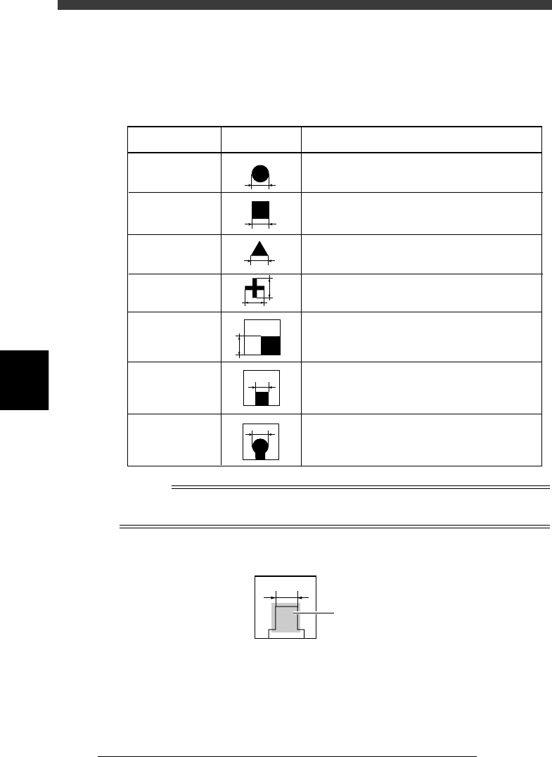
Mark OutSize settings
25514-C0-00
Example MarkOutSize settingShape type
Circle
Square
Triangle
Sp. Shape
Corner
TopEdge
CirEdge
Enter the diameter.
Enter the length of one side.
Enter the length of one side.
Enter the X length for the MarkOutSize X, and
the Y length for the MarkOutSize Y.
Enter the length of the shorter side displayed
within the search area.
Enter the length of the shortest side from among
the three sides displayed within the search area.
Enter the diameter of the round edge.
X
Y
Reference
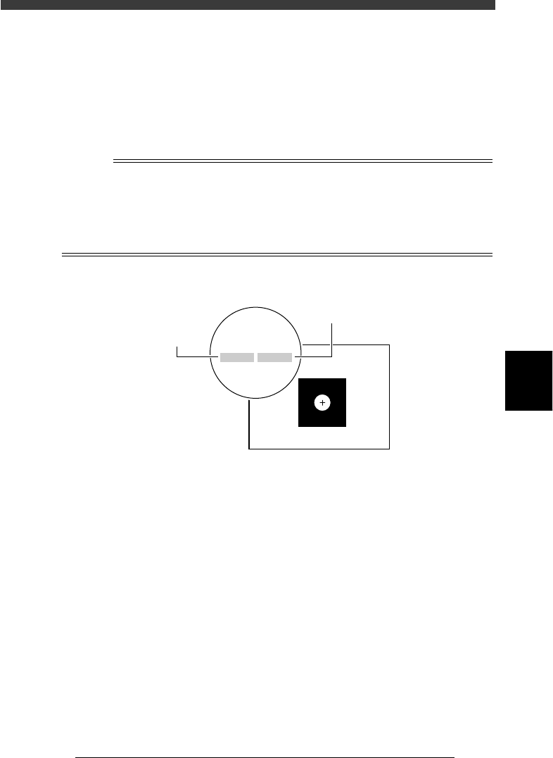
If you use a special mark with two or more edges as shown below, enter the size of the
shortest side of the rectangular area you want to detect
Mark OutSize setting for special mark
23532-C0-00
Rectangular area
to be detected
5
-81
EPD8013110
Operation
Chapter 5
5
Creating the PCB data
9. Mark Area
Enter here the area of the mark in units of square millimeters. This
parameter is displayed only when the Shape Type in the Vision Info. sub-
window is set to “Sp. Shape”.
10. Perimeter
Enter here the perimeter length of the mark in units of millimeters.
This parameter is displayed only when the Shape Type in the Vision Info.
sub-window is set to “Sp. Shape”.
n
Note
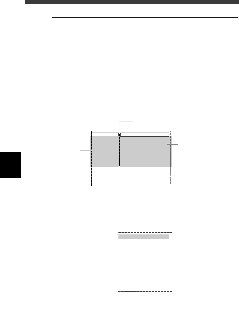
A recognition error may occur due to environmental conditions such as illumination. In
such cases, enter a larger value than previously used for the “Tolerance” parameter in the
Vision Info. sub-window, or set the tolerance to 100%, then perform “VISION TEST” in
the Adjust Assistant and enter the obtained data on the area and perimeter. (The mark
area and perimeter values are displayed after VISION TEST as shown below.) Return the
tolerance to the original value after the data is obtained.
Mark area and perimeter display
23533-C0-00
XC:257.2
area:0.74
YC:258.7
peri:3.21
XC:257.2
area:0.74
YC:258.7
peri:3.21
Perimeter
Area
5
-82
EPD8013110
Operation
Chapter 5
5
Creating the PCB data
4.3 Adjust Assistant commands
This operation checks whether the parameter settings are correct. For
parameters which are unspecified, the optimal values can be obtained by
performing “VISION TEST” here. The following adjustment procedure is
explained for cases where the “Mark Type” parameter in the Mark Type
Info. sub-window is set to “Fiducial”.
1 Select the mark data.
Move the cursor to the data you want to check on the Mark Info.
screen.
2 Open the Adjust Assistant screen.
Press the [F6] key to run the <2/1/B1 ADJUST ASSISTANT> command. The
Adjust Assistant screen appears as shown below.
Adjust assistant (mark) screen
27534-D8-00
Adjust Assist Items
Mark Threshold
Tolerance (%)
Search Area (mm)
Outer Light Level
Inner Light Level
Axial Light Level
IR Outer Level
IR Inner Level
127
30
4.00
Mark Name : FIDUCIAL
Standard
Standard
Standard
Standard
Standard
V180
Then, select "TEACH MARK".
Command
FIX PCB
TEACH MARK
VISION TEST
PARAM. SEARCH
*
*
CHK THRESHOLD
EXIT
Message and results are
displayed here.
Adjust
Assistant
commands
Parameters
specified in
Mark Info.
Name of selected mark
3 Clamp the PCB in place.
Run “FIX PCB” of the Adjust Assistant commands and select the conveyor
table. The conveyor unit menu box appears.
Conveyor unit menu box
27535-C0-00
LOCATE PIN
PUSH UP
PCB CLAMP
EDGE CLAMP
PUSH IN
MAIN STOPPER
ENT. STOPPER
EXIT STOPPER
CONV. MOTOR
CONV. WIDTH
PROGRAM PIN
RETURN
CONVEYOR UNIT (STS.)
OFF
OFF
OFF
OFF
OFF
OFF
OFF
OFF
OFF
OFF