YV180X_Ope_E.pdf - 第58页
4 -19 EPD8013110 Operation Chapter 4 4 Daily operation • Password Levels A, B and C: The monitor shows for each head, the component No. being picked up by the head, feeder type and set position, and error code if an erro…
4
-18
EPD8013110
Operation
Chapter 4
4
Daily operation
4
3. PRODUCTION MONITOR
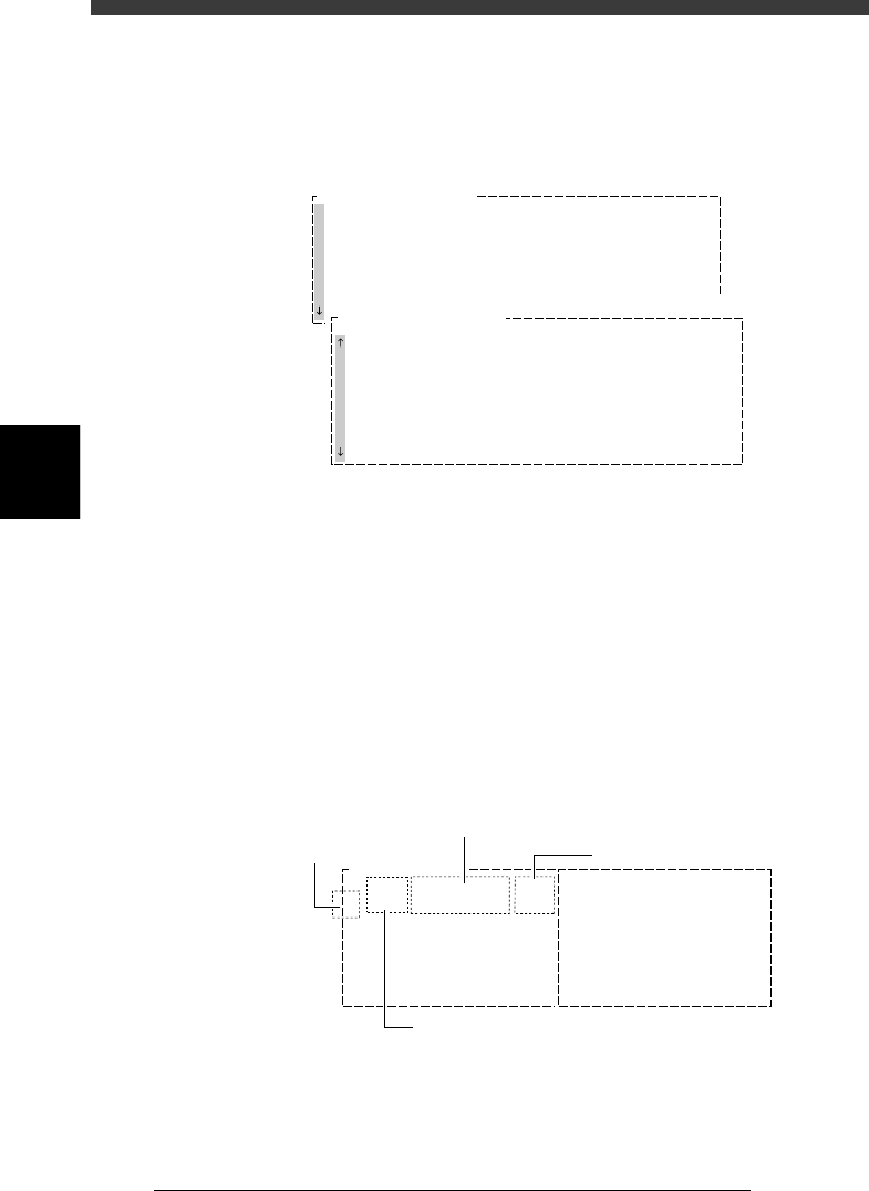
The PRODUCTION MONITOR shows information on PCB production in
progress. To see the next or previous screen, press the [PageUp] or
[PageDown] key ([Fn]+[
↑
] or [Fn]+[
↓
] keys).
PRODUCTION MONITOR window
27409-C0-00
PRODUCTION MONITOR
PCB/SCHEDULE/BLOCK
UNLOADER COUNT/MAX
TOTAL TACT(sec/pcb)
SET PCB(sec/pcb)
WAITING(sec/pcb)
0
0
0
0
0
PRODUCTION MONITOR
Component Name SetNo.
F20
F21
F23
F24
F25
F26
F27
F28
Count
12
20
10
40
12
10
0
1
Error
0
0
0
0
0
0
0
0
Pallet Counter/Total
1
2
3
4
5
6
7
8
4. VISION MONITOR
The VISION MONITOR informs you of the component recognition status
of the vision system. The contents displayed in this window depend on the
password level.
• Password Level D:
The monitor shows the XYR offset values for each head which are detected
to correct the position of a component picked up and also shows error
code if an error occurred. Error numbers are indicated in the CEME
column. For the meaning of each number displayed in the box, place the
cursor on the <1/1/C1 AUTO RUNNING MONITOR> - ”MONITOR
VISION” and press the [F1] key to see the help message.
VISION MONITOR window (1)
27410-C0-00
Comp
7
X
-0.03
Y
-0.10
R
-0.05
CEME
0
1
Comp
21
X
-0.30
Y
0.02
R
0.12
CEME
1-22
VISION MONITOR
Offset detected by vision system
Head No.
Error code
Component No.
4
-19
EPD8013110
Operation
Chapter 4
4
Daily operation
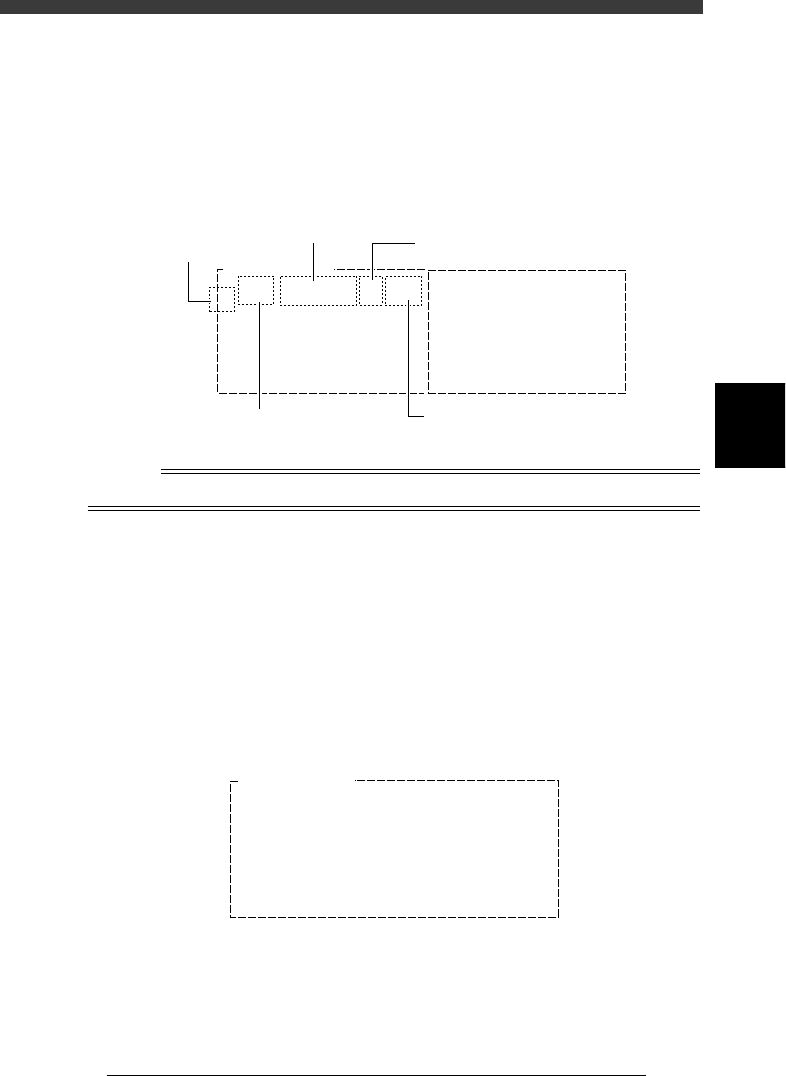
• Password Levels A, B and C:
The monitor shows for each head, the component No. being picked up
by the head, feeder type and set position, and error code if an error
occurred. Error numbers are indicated in the CEME column. For the
meaning of each number displayed in the box, place the cursor on the
<1/1/C1 AUTO RUNNING MONITOR> - ”MONITOR VISION” and
press the [F1] key to see the help message.
VISION monitor (2)
27411-C0-00
Feeder Type
8mmTape
Set
12
Comp
7
CEME
0
1
Comp
21
Feeder Type
8mmTape
CEME
1-22
VISION MONITOR
Set
16
Component No.
Feeder type
Feeder set No.
Head No.
Error code
Reference
Refer to “2. Setting the password” in Chapter 2 for details on password setting.
5. Retry monitor (1/1/C5 MONITOR RETRY)
The RETRY MONITOR shows the following information.
• Error type (pickup error or recognition error) that called for a retry
• Message when alternative components have run out
• Feeder plate conditions when non-stop function is used
• Message when dump station (option) is full.
Up to 20 errors are displayed in the order that each error occurred.
To see the next or previous screen, press the [PageUp] or [PageDown] key
([Fn]+[
↑
] or [Fn]+[
↓
] keys).
RETRY MONITOR window
27412-C0-00
RETRY MONITOR
ERROR Component Name Feeder No. Time
08
07
06
05
04
03
02
01 R2125 17 17:23
4
-20
EPD8013110
Operation
Chapter 4
4
Daily operation
4
6. BIGNUM MONITOR
This monitor shows information on the PCB count, block repeat No. and
cycle time for the PCB for which component mounting is in progress.
BIGNUM MONITOR screens showing the PCB count, cycle time, etc.
27413-C0-00
msec/chip
BLOCKs
PCBs
PCB count
Block repeat No.
Cycle time
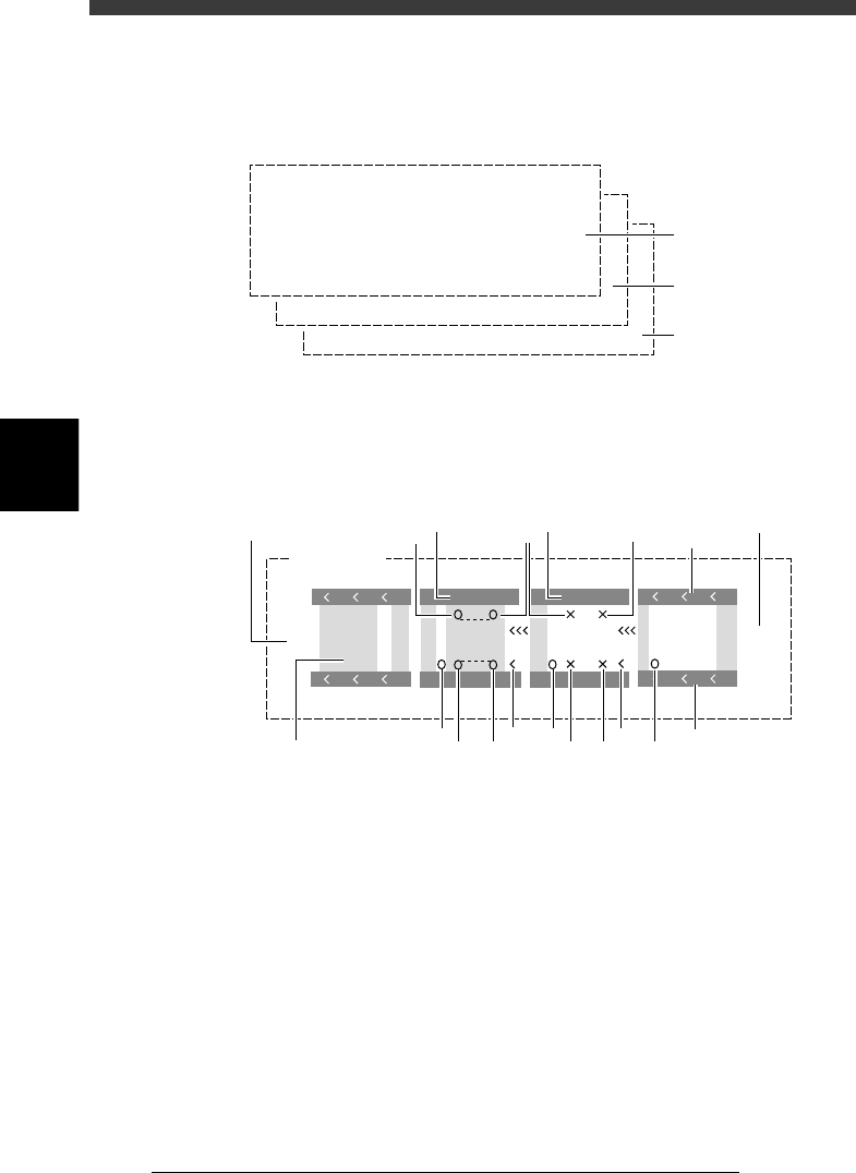
7. CONV. MONITOR
This monitor shows the current conveyor operation status.
Conveyor monitor
27414-C0-00
Gate
out
Gate
in
CONV. MONITOR
A Table
B Table
VV
VV
1
3 3
1
2
2
464
5 5 5 5
6
7
9
8
10
1
1. Push-up
O : ON, X : OFF (This is not displayed when the PCB clamping
method “PcbFixDevice” in the PCB Info. is set to “Locate Pin”.
2. Conveyor motor
Shows the operation status of the conveyor motor for PCB transfer.
When the conveyor motor is operating, the symbols “< < <“ move in
the PCB flow direction.
3. Edge clamp (option)
V : ON, No display : OFF
4. Main stopper
O : ON, No display : OFF
5. Locate pin
O : ON, X : OFF