YV180X_Ope_E.pdf - 第73页
4 -34 4 Operation Chapter 4 4 Daily operation EPD8013110 8.7 Edge clamp (option) The edge clamp secures the PCB in the mounting position by pushing laterally on the PCB edge. If necessary , adjust the position of each ed…
4
-33
Operation
Chapter 4
4
Daily operation
EPD8013110
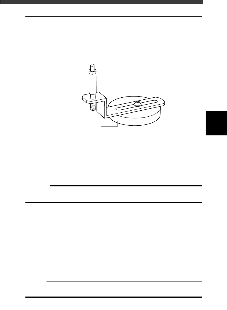
8.6 Push-up pins
The push-up pins are attached to the push-up plate by a magnet and used to
correct downward warping of the PCB. (When using these push-up pins,
set the PCB FixDevice parameter on the PCB Info. screen to “Pin+Push-
UP” or “Edge Clamp” (option).)
Push-up pin
23414-D8-00
Magnet stand
Pin shaft
e
1
Check that the machine is in emergency stop.
If not, press the emergency stop button.
2
Place the push-up pins in correct position on the push-up
plate.
Considering the shape and size of the PCB, place the push-up pins on the
push-up plate so that they uniformly support the PCB, including the edge
of the PCB.
c
CAUTION
Set the push-up pins in positions where they will not interfere with the conveyor rails
and other parts when the push-up plate is raised.
3
Set a PCB on the conveyor.
Raise the main stopper with the MAIN STOPPER command in the
CONVEYOR UNITS menu, then set a PCB on the conveyor and place it
against the main stopper.
4
Raise the push-up plate.
Use the PUSH UP command in the CONVEYOR UNIT menu to raise the
push-up plate.
5
Check that the PCB is uniformly clamped on the conveyor.
Lightly tap on the PCB and also check for warping of the PCB from the
side. If the PCB is supported evenly with no warping, the adjustment is
okay.
Reference
It may be convenient to mark the positions of the push-up pins on the plate (with a label,
magic marker, etc.) for each PCB type.
4
-34
4
Operation
Chapter 4
4
Daily operation
EPD8013110
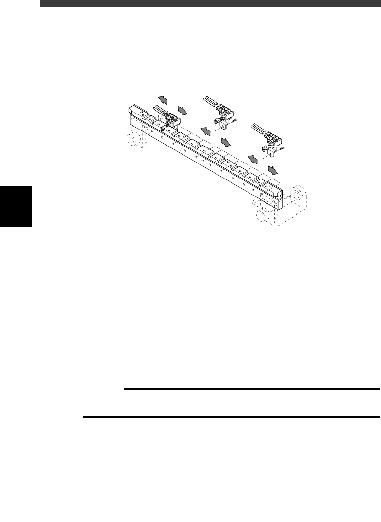
8.7 Edge clamp (option)
The edge clamp secures the PCB in the mounting position by pushing
laterally on the PCB edge. If necessary, adjust the position of each edge
clamp unit according to the size of the PCB.
Edge clamp
23415-D8-00
Edge clamp
M2.5 bolt
e
1
Check that the machine is in emergency stop.
If not, press the emergency stop button.
2
Place the push-up pins in correct position on the push-up
plate.
Considering the shape and size of the PCB, place the push-up pins on the
push-up plate so that they will uniformly support the PCB.
3
Set a PCB on the conveyor.
Raise the main stopper with the MAIN STOPPER command in the
CONVEYOR UNIT menu, then set a PCB on the conveyor and place it
against the main stopper.
4
Raise the push-up plate.
Use the PUSH UP command in the CONVEYOR UNIT menu to raise the
push-up plate.
c
CAUTION
Before raising the push-up plate, check that the push-up pins are set in positions where
they will not interfere with the conveyor rails and other parts
5
e
Remove the edge clamp whose position should be changed.
Loosen and remove the bolt securing the edge clamp and remove the edge
clamp along with the stay.
6
Reattach the edge clamp.
Attach the edge clamp in the proper position and tighten the bolt.
7
Check that the PCB is uniformly clamped on the conveyor.
Use the EDGE CLAMP command in the CONVEYOR UNIT menu to check
whether the PCB edge is securely clamped.
4
-35
Operation
Chapter 4
4
Daily operation
EPD8013110
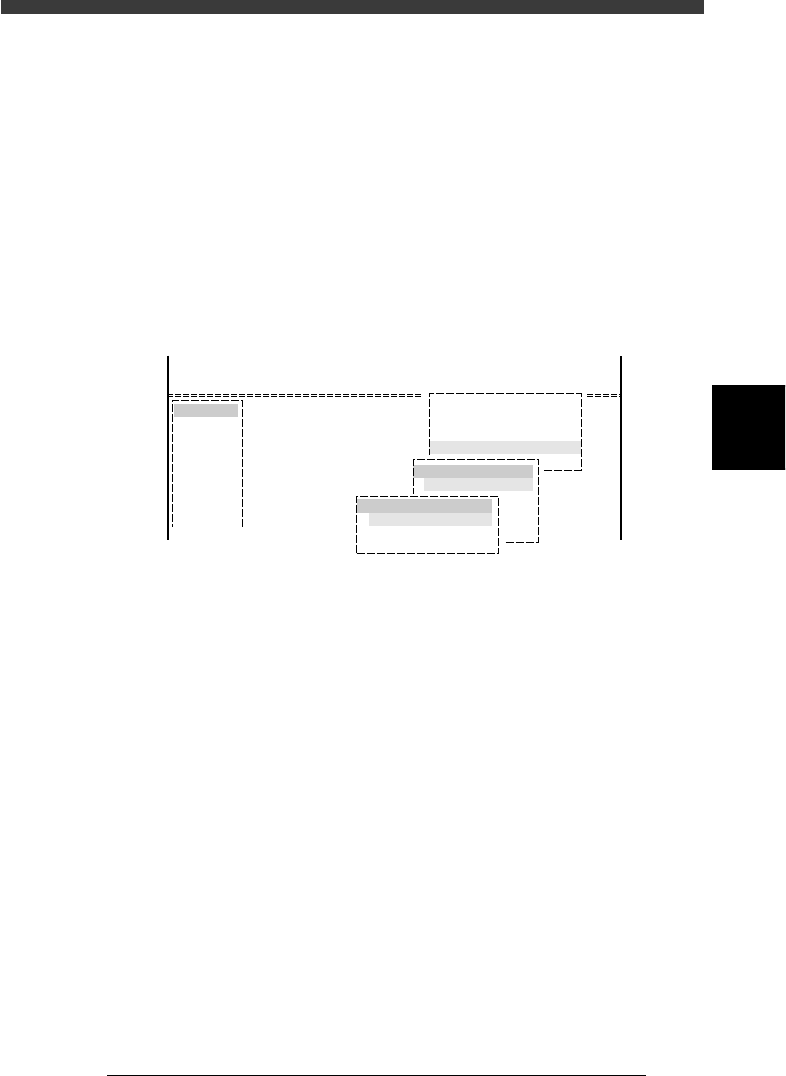
9. HALFWAY CONTINUE command
The HALFWAY CONTINUE command in the <1/1/D5 STOPPING
UTILITY> allows you to remount components with mounting data that has
been reset during PCB production, or perform mounting for a specific
block or mount point. There are two occasions you can select for executing
this command as explained below.
Note that the HALFWAY CONTINUE command can be used just for the
first PCB, with routine mounting operation beginning from the next PCB.
To quit this command, select “RETURN” from the HALFWAY CON-
TINUE menu box and press the [ENTER] key.
HALFWAY CONTINUE command
27417-C0-00
<<<APPLICATION>>> 1/OPERATION/M
<<MODE>> 1/RUNNIG
<<COMMAND_LIST>>
Condition
D/INITIALIZE
D5 STOPPING UTILITY
STOPPING UTILITY
HALFWAY CONTINUE
HALFWAY CONTINUE
LOAD SAVED CONDITION
MNT FLAG EDITOR
RETURN