YV180X_Ope_E.pdf - 第193页
5 -117 EPD8013110 Operation Chapter 5 5 Creating the PCB data 10. Mounting test and data correction Component mounting test should be performed to confirm that the produc- tion data is correct. Follo w the flow char t be…

5
-116
EPD8013110
Operation
Chapter 5
5
Creating the PCB data
9.3 Optimizing the data
When you have selected the PCB and setting conditions, perform the data
optimization in the DATA GENERATOR mode.
1 Perform data optimization.
1. Select <2/2/A5 EXECUTE> and press the [ENTER] key.
The DATA GENERATOR SEQUENCE MONITOR box appears to start
the data optimization. When the optimization is complete, the
mounting data such as mounting cycle and number of mounting points
is displayed.
2. Press any key to return to the previous screen.
DATA GENERATOR monitor box and optimized results
27547-C0-00
DATA GENERATOR SEQUENCE MONITOR
PCB NAME PCB1 MACHINE
18. DISTRIBUTING MOUNT DATA
>>>>>>>>>>>>
2 Save the data.
Select <2/2/C5 RENAME & EXIT> and press the [ENTER] key. The opti-
mized data will be saved.
c
CAUTION
The original data will be overwritten when the optimized data is saved with the <2/2/C0
SAVE & EXIT> command. To keep the original data, rename and save the data with the
<2/2/C5 RENAME & EXIT> command.
5
-117
EPD8013110
Operation
Chapter 5
5
Creating the PCB data
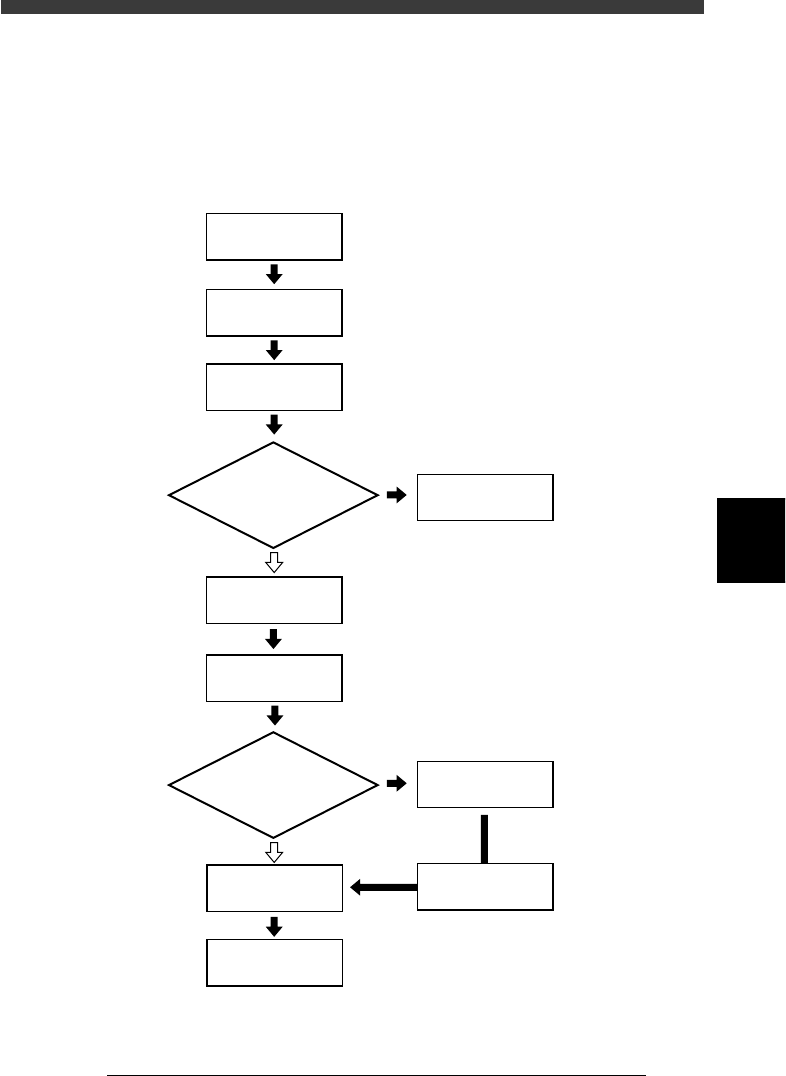
10. Mounting test and data correction
Component mounting test should be performed to confirm that the produc-
tion data is correct. Follow the flow chart below to perform the mounting
test and data correction.
Mounting test and data correction flow
23552-C0-00
Setup
Select
1/RUNNING
Start operation
Complete component
mounting
PCB data error?
Error ?
Correct PCB data
10.3
☞
10.3
☞
10.4
☞
Preparation for
mounting test
Select PCB name
Correct data
Execute 1/1/E4
Halfway continue
Check mounting
results and correct data
YES
YES
NO
NO
5
-118
EPD8013110
Operation
Chapter 5
5
Creating the PCB data
10.1 Making setups for mounting test
Before starting mounting test, select the PCB data and make necessary
setups.
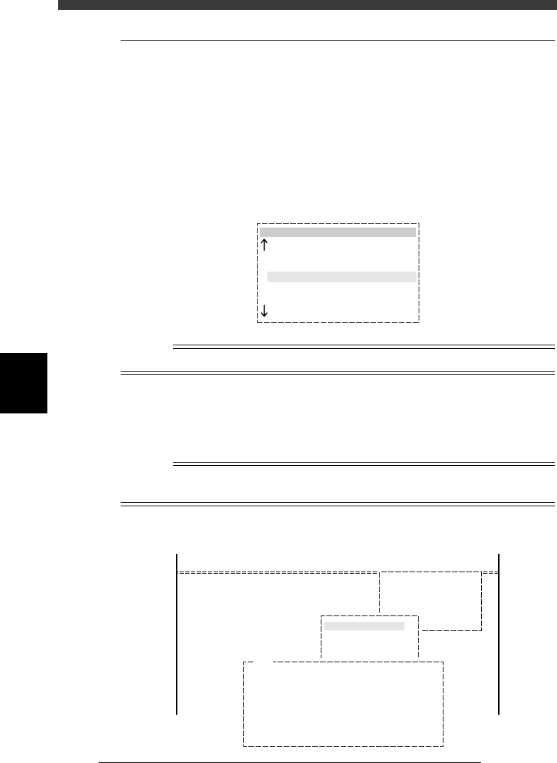
1 Enter the <1/1/RUNNING> mode and select the PCB
name.
When you enter the <1/1/RUNNING> mode, a list of PCB names appears.
Select the PCB to be produced and press the [ENTER] key, then the PCB
data will be loaded. If an error occurs during data loading, refer to section
“10.3.1 Error countermeasures” in this chapter.
PCB name box
27548-C0-00
pcb name
CONVEYOR
ANC_TEST
PALLET_88
PCB1
1994-08-16
1998-02-11
1998-02-23
1997-11-24
n
NOTE
To change the production PCB, press the [F2] key.
2
e
Check the nozzle type attached to each head.
Check whether the correct nozzle is attached to each head. If not, press
the emergency stop button and fit the correct nozzle to each head by
hand.
Reference
To see the list of nozzles to be used, select <1/1/D4 ASSISTANT UTILITY> - ”REQUIRED
NOZZLE” and press the [ENTER] key.
List of nozzles to be used
27549-C0-00
<<MODE>> 1/RUNNING
<COMMAND_LIST>
D/INITIALIZE
D4 ASSISTANT UTILITY
ASSISTANT UTILITY
REQUIRED NOZZLES
Current nozzles o n heads may be . . .
A TABLE : [ Upper = Head No. , Lower = Nozzle Type ]
Head 1 2 3 4 5 6 7 8
Nzl. 72 0 72 0 72 0 72 0
B TABLE : [ Upper = Head No. , Lower = Nozzle Type ]
Head 1 2 3 4 5 6 7 8
Nzl. 72 0 72 0 72 0 72 0
E151