YV180X_Ope_E.pdf - 第39页
3 -8 EPD8013110 Operation Chapter 3 3 Manual operation 3. Feeder operation Feeder operation can be checked with the <A4 FEEDER ON/OFF> command in MANU AL mode. 1 Select MANUAL mode. The MANUAL mode is available in …
3
-7
EPD8013110
Operation
Chapter 3
3
Manual operation
2. Conveyor unit operation
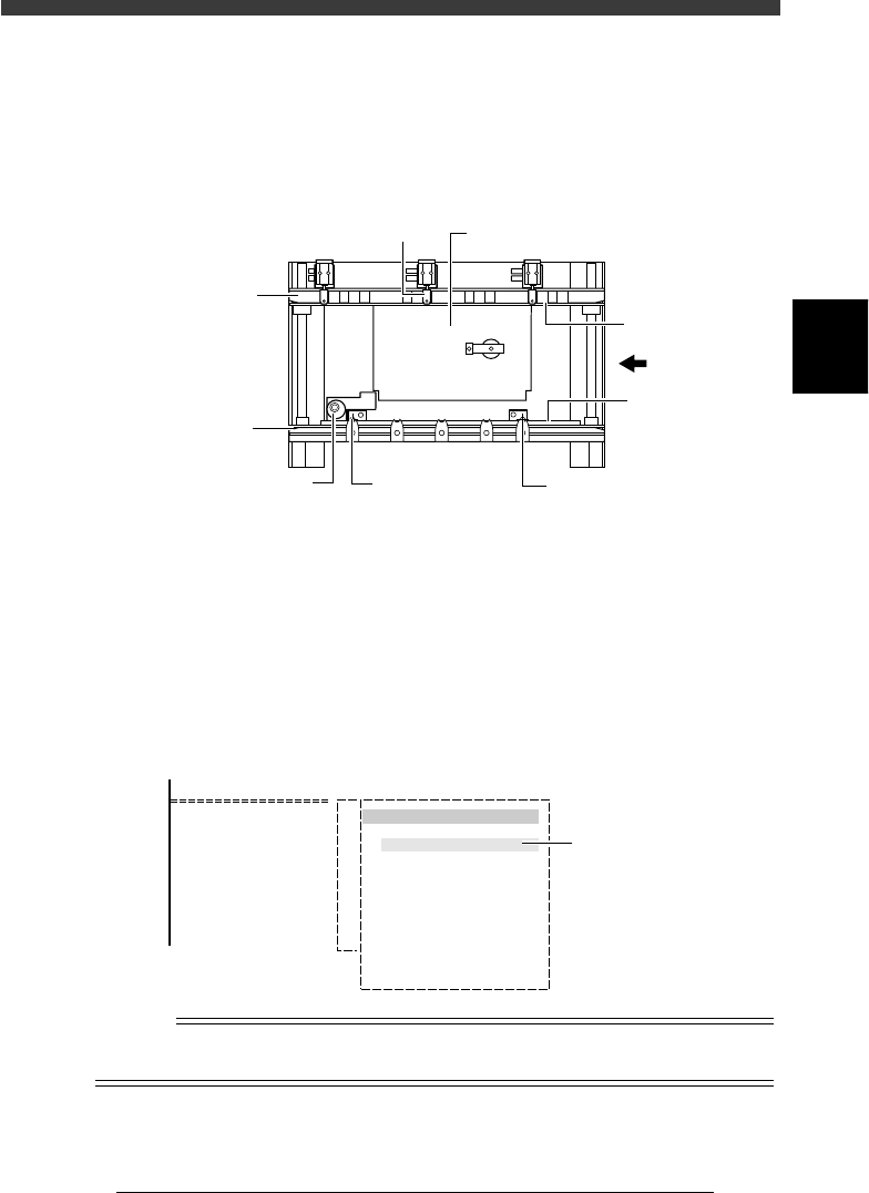
The conveyor units such as main stopper, push-up unit and locate pins can
be operated manually with the CONVEYOR UNITS commands.
Conveyor units (Top view)
23303-D8-00
PCB
Push-up plate
Edge clamp
PCB clamp
PCB clamp
Movable locate pinFixed locate pinMain stopper
Fixed
conveyor rail
Movable
conveyor rail
1
Select <2/1/B7 CONVEYOR UNITS>.
The conveyor units can also be operated by selecting the <1/1/D4
ASSISTANT UTILITY> - “CONVEYOR UNITS” command.
2
Move the cursor to the unit to be operated and press the
[ENTER] key.
Each time you press the [ENTER] key, the selected unit alternately switches
on or off. The sensor detection status is indicated to the right of each unit.
Conveyor unit selection box
27304-C0-00
<COMMAND_LIST>
B/UTILITY
B7 CONVEYOR UNITS
CONVEYOR UNIT
LOCATE PIN
PUSH UP
PCB CLAMP
EDGE CLAMP
PUSH IN
MAIN STOPPER
ENT. STOPPER
EXIT STOPPER
CONV. MOTOR
CONV. WIDTH
PROGRAM PIN
RETURN
(STS.)
OFF
ON
OFF
OFF
OFF
OFF
OFF
OFF
OFF
OFF
Sensor detection
status
Reference
The conveyor unit can also be operated from the <A1 INPUT/OUTPUT MONITOR> in
MANUAL mode.
3
-8
EPD8013110
Operation
Chapter 3
3
Manual operation
3. Feeder operation
Feeder operation can be checked with the <A4 FEEDER ON/OFF>
command in MANUAL mode.
1
Select MANUAL mode.
The MANUAL mode is available in the OPERATION, DATA and MAINTE-
NANCE Managers.
2
Select <A2 FEEDER OUT MONITOR> from the <A/IO
UTILITY> menu window.
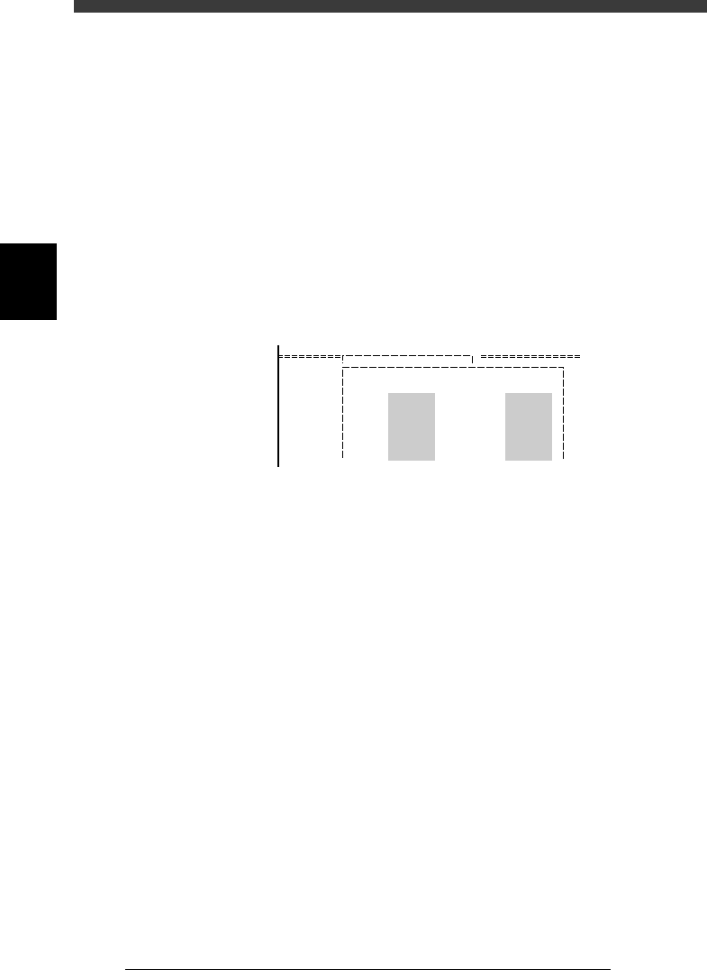
The screen below appears when this command is selected. The left-hand
numbers (from 1) show the front feeder plate set numbers and right-hand
numbers (from 101) the rear feeder plate set numbers.
FEEDER OPERATION screen
27305-C0-00
<COMMAND_LIST> A/IO_UTILITY
< FEEDER OPERATION >
101 - 108
109 - 116
117 - 124
125 - 132
133 - 140
141 - 148
1 - 8
9 - 16
17 - 24
25 - 32
33 - 40
41 - 48
00000000
00000000
00000000
00000000
00000000
00000000
00000000
00000000
00000000
00000000
00000000
00000000
3
Move the cursor to the feeder to be operated and press the
[ENTER] key.
1. Using the arrow keys, place the cursor on the feeder set number
you want to operate and press the [ENTER] key. (To move the cursor
between the left-hand and right-hand numbers, press the [TAB] or [SPACE]
key.)
2. Digit “0” of the selected feeder changes to “1” and the feeder pneu-
matically operates to open the shutter.
3. To turn off the feeder, press the [ENTER] key again.
Digit “1” changes to “0” and air supply stops to close the shutter.
3
-9
EPD8013110
Operation
Chapter 3
3
Manual operation
4. Operating the I/O monitor
The I/O monitor in MANUAL mode is useful for checking the mounter
operation status or switching mechanical parts on or off manually. The
following explains how to read or operate the digital signal output monitor
in MANUAL mode. (For more information, refer to the mounter service
manual.)
1
Select MANUAL mode.
The MANUAL mode is available in the OPERATION, DATA and MAINTE-
NANCE Managers.
2
Select <A1 INPUT/OUTPUT MONITOR> from the <A/IO
UTILITY> menu window.
The DISP. TYPE box appears for selecting the display method.
3
Select the display method.
There are two display methods, “ALL” and “SELECTION”.
Selecting “ALL” allows you to view all the digital I/O status.
Selecting “SELECTION” displays the submenu from which you can select
the specific group (such as “CONVEYOR” and “HEAD”).
4
Move the cursor to the item you want to check or operate.
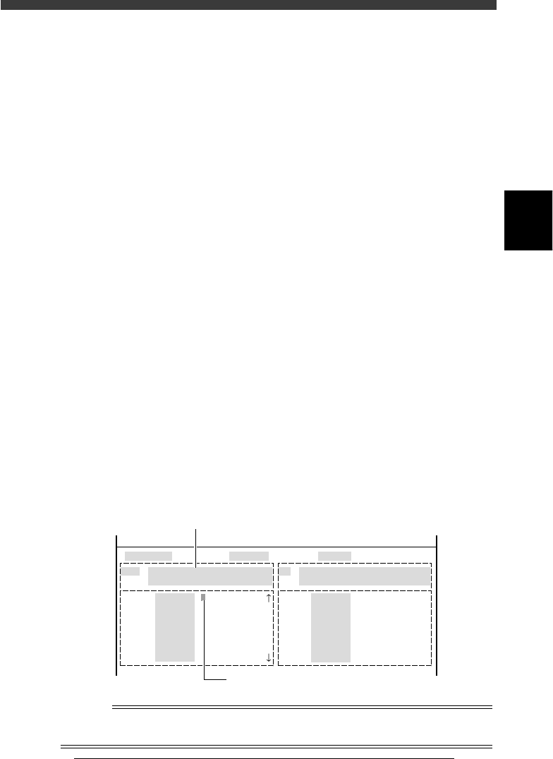
When the I/O monitor is displayed, use the arrow keys to align the yellow
cursor with the item you want to check or operate. A description is
displayed in a light blue box on the screen, giving the item of the reading
and an explanation of what “0” and “1” correspond to.
5
Press the [ENTER] key to switch on and off.
Each time you press the [ENTER] key, the digit on which the cursor is
positioned switches between “0” and “1”.
To move the cursor between the output and input monitors, press the
[TAB] key.
Output monitor (left) and input monitor (right) screen
27306-C0-00
HEAD
....
....
....
....
....
....
....
OUT
00000000 ....
....
....
....
....
....
....
....
IN
T2A30
.....
.....
.....
.....
.....
.....
.....
N2260
.....
.....
.....
.....
.....
.....
.....
I/O MONITOR DISP. TYPE SELECTION
Head-A HEAD 1-8 BLOW
USUAL 0 / BLOW 1
HEAD
....
....
....
....
....
....
....
OBJECT HEAD
<<MODE>> 4/MANUAL
Use the arrow keys to move the cursor.
Description of selected item
Reference
Each time you press the [TAB] key, the yellow cursor moves between the left-half output
monitor and the right-half input monitor to switch the active monitor.