YV180X_Ope_E.pdf - 第66页
4 -27 Operation Chapter 4 4 Daily operation EPD8013110 8.1 Conveyor unit setup flow When changing the con ve yor unit setups, use <1/1/D4 ASSIST ANT UTILITY> in R UNNING mode. The flow chart belo w shows a typical …
4
-26
4
Operation
Chapter 4
4
Daily operation
EPD8013110
8. Changing the conveyor unit setup
When switching the PCB type, the conveyor unit must be set up correctly
according to that PCB type. This section describes how to change the
conveyor unit setups. To change feeder setups, refer to the separate
“FEEDER” user’s manual.
About PCB clamping method
The conveyor units to be adjusted differ depending on the PCB clamping
method you use. There are three methods for clamping the PCB on the
conveyor.
• Pin + Push-UP
The PCB is clamped with the locate pins, push-up pins and PCB clamp.
• Locate Pin
The PCB is clamped only with the locate pins.
• Edge Clamp (option)
The PCB is clamped from the edge. The push-up pins and PCB clamp can be
used but the locate pins do not work.
Reference
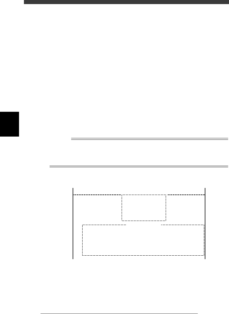
In <1/1/RUNNING> mode, you can check the PCB clamping method by executing the <1/
1/B6 RUNNING CONDITION> command after selecting the PCB data.
You can also specify the PCB clamping method on the PCB Info. screen. (See “6. Creating
the PCB information” in Chapter 5.)
Checking the PCB clamping method
27415-C0-00
<<MODE>> 1/RUNNING
<COMMAND_LIST>
B/CONDITION
B6 RUNNING CONDITION
PcbFixDevice
Running Condition Editor
A/RUNNING
Pin+PushUP
4
-27
Operation
Chapter 4
4
Daily operation
EPD8013110
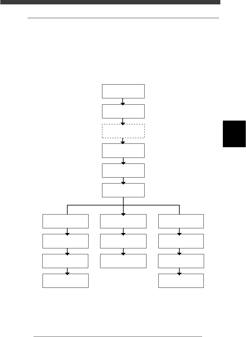
8.1 Conveyor unit setup flow
When changing the conveyor unit setups, use <1/1/D4 ASSISTANT
UTILITY> in RUNNING mode. The flow chart below shows a typical
sequence for setting up the conveyor units. Select the PCB clamping
method according to the PCB type to be produced, and adjust each con-
veyor unit to be used. The method for adjusting each conveyor unit is
described in the following sections “8.2” to “8.7”.
Typical flow chart for changing the conveyor unit setups
23409-D8-00
Adjust
conveyor width
Press emergency
stop button
Raise main stopper
* PCB clamping method
Adjust locate pin
Adjust PCB
support plate
Adjust edge clamp
Adjust push-up pin
Adjust PCB
support plate
Pin+PushUP * Edge Clamp *
Select PCB
Use this command as needed.
Select <1/1/D4
ASSISTANT UTILITY>
Run
"MOVE ON FEEDER"
Adjust locate pin
Adjust PCB
support plate
Locate Pin *
Adjust push-up pin
Adjust transfer hook
Adjust transfer hookAdjust transfer hook
4
-28
4
Operation
Chapter 4
4
Daily operation
EPD8013110
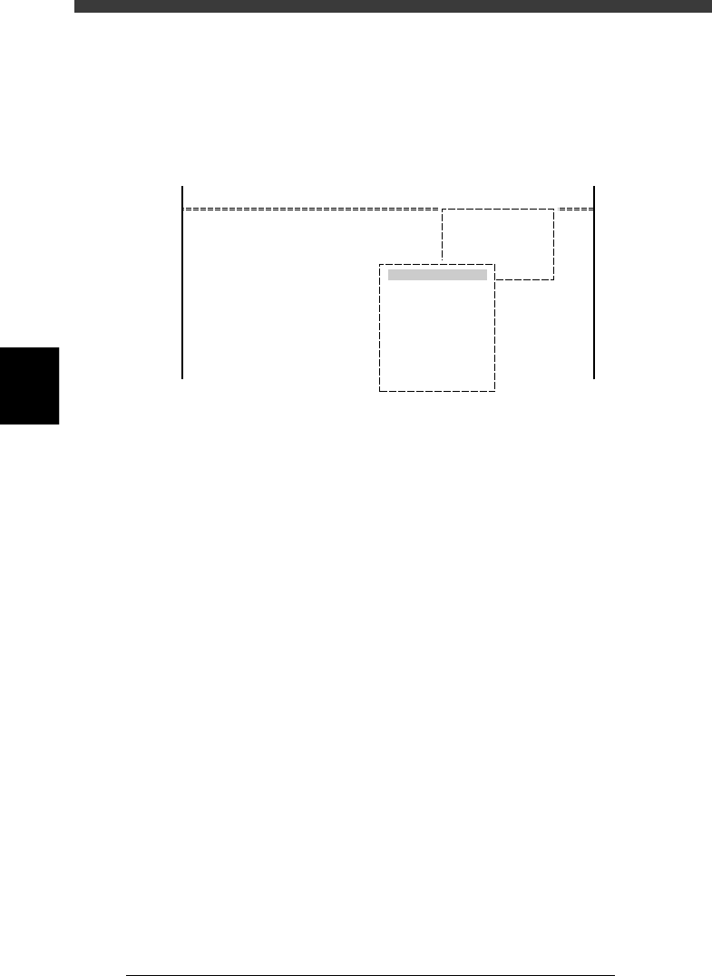
● MOVE ON FEEDER and MOVE ON PCB TABLE commands
To make conveyor unit and feeder setups easier, the MOVE ON FEEDER
and MOVE ON PCB TABLE commands were added to the <1/1/D4
ASSISTANT UNTILITY> menu. Use these commands as needed when
changing the conveyor unit and feeder setups.
MOVE ON FEEDER and MOVE ON PCB TABLE commands
27420-D8-00
D/INITIALIZE
D4 ASSISTANT UTILITY
ASSISTANT UTILITY
MOVE ON FEEDER
MOVE ON PCB TABLE
<<MODE>> 1/RUNNING
<COMMAND_LIST>
MOVE ON FEEDER : Moves the head assembly to above the feeder plate
and the conveyor table to the front side.
MOVE ON PCB TABLE : Moves the head assembly to above the PCB clampin
g
position.