YV180X_Ope_E.pdf - 第101页
5 -25 EPD8008100 Operation Chapter 5 5 Creating the PCB data For descriptions of the following PICK & MOUNT INFO. parameters, refer to “ 3.3.1 Standard chip components ” in this chapter . 22. Pick Timer , Mount Timer…
5
-24
EPD8008100
Operation
Chapter 5
5
Creating the PCB data
1. BASIC INFO. parameters
For descriptions of the BASIC INFO. parameters other than “3 Required
Nozzle”, refer to “3.3.1 Standard chip components” in this chapter.
1. Comp. Package
2. Feeder Type
3. Required Nozzle
4. Feeder Set No.
5. Pos. Definition
6. Feeder Pos_X
2. OPTION INFO. parameters
For descriptions of the following OPTION INFO. parameters, refer to
“3.3.1 Standard chip components” in this chapter.
11. FixCmpRef.
12. Alt. Comp.
13. Use feeder opt.
14. Comp. Group No.
15. Correct Pickpos.
3. PICK & MOUNT INFO. parameters
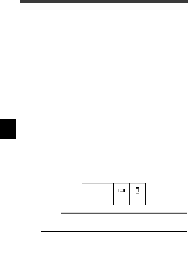
21. Pick Angle deg
This parameter specifies the angle through which the mounter head rotates
to pick up a component on the feeder. This setting determines the orienta-
tion of the component (recognition reference) when it is recognized and
displayed on the vision monitor. Normally, set this parameter to 0° for
horizontally long components in the loading position, and set to 90° for
vertically long components. Select the correct pickup angle referring to the
table below.
Melf component pickup angle
25504-C0-00
0 deg. 90 deg.
Loading position
Pickup angle
NS
E
W
N
S
WE
c
CAUTION
Pickup angle setting directly affects the recognition reference and mounting angle. Be
careful not to mistake 0° for 180° for horizontally long components in the loading
position and 90° for -90° for vertically long components.

5
-25
EPD8008100
Operation
Chapter 5
5
Creating the PCB data
For descriptions of the following PICK & MOUNT INFO. parameters,
refer to “3.3.1 Standard chip components” in this chapter.
22. Pick Timer, Mount Timer
23. Pick Height, Mount Height
24. Pick Sequence
25. Mount Action
26. Vacuum Check
27. Pick Vacuum, Mount Vacuum
These are reference vacuum pressures used for checking the pickup and
mount vacuum levels. For more details, see “3.7 Adjust Assistant com-
mands“ and “3.9 Pickup and mount vacuum pressures” in this chapter.
28. Conv. Y Speed
4. DUMP INFO. parameters
31. Dump Way
Set to “Dump POS”. Refer to the Discard point parameter explained in the
mounter service manual.
32. Retry Times
See the description of “3.3.1 Standard chip components”.
5. VISION INFO. parameters
41. Alignment Group
Set this parameter to “Chip”.
42. Alignment Type
Set this parameter to “Melf Chip”.
43. AlignmentModule
This parameter specifies the lighting method for recognizing a component.
Use the default setting (Fore&Back&Laser) in most cases. Refer to the
description in “3.3.1 Standard chip components” for more details.
For descriptions of the following VISION INFO. parameters, refer to
“3.3.1 Standard chip components”.
44. Light Selection
45. Lighting Level
46. Comp. Threshold
47. Comp. Tolerance
48. Search Area
49. Datum Angle
50. Comp. Intensity
51. MultiCam Marker
5
-26
EPD8008100
Operation
Chapter 5
5
Creating the PCB data
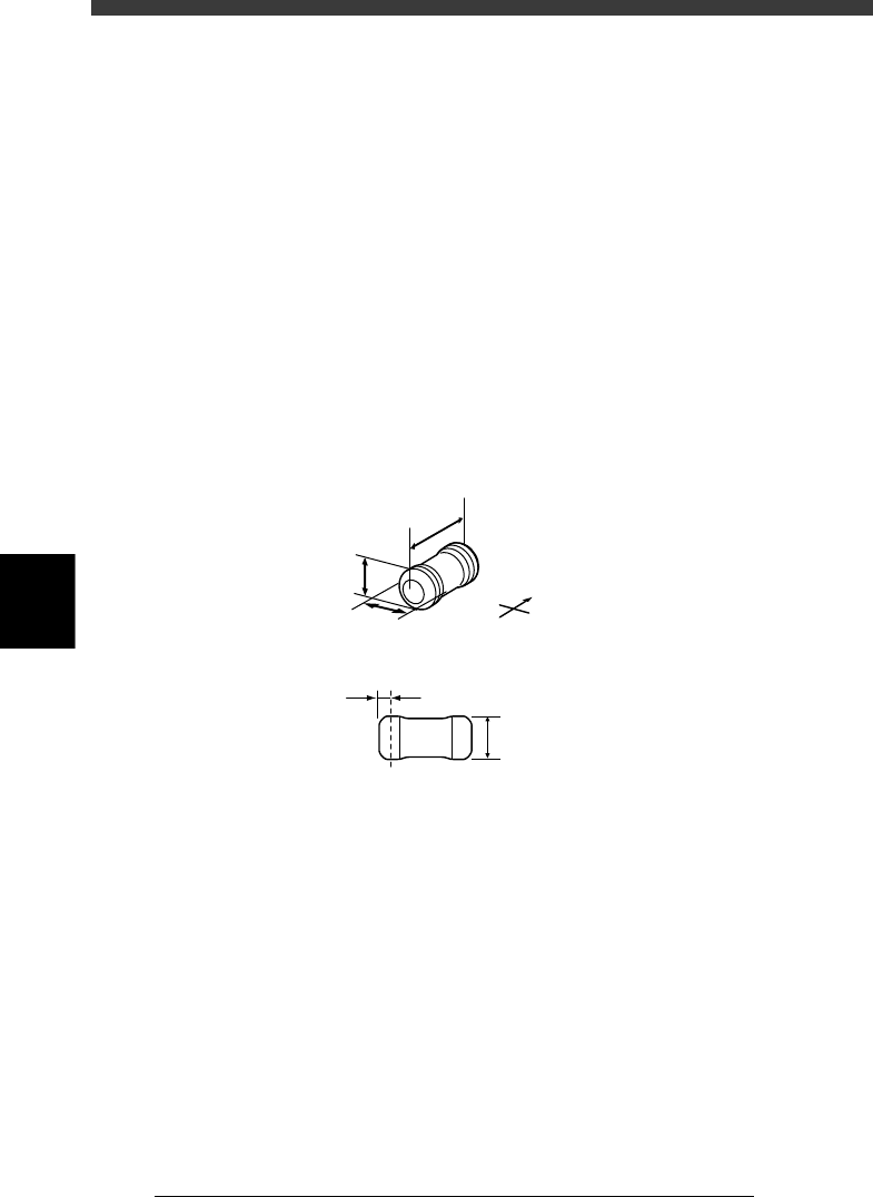
6. SHAPE INFO. parameters
Set these parameters after specifying the VISION INFO. parameters. If
“Alignment Type” is undefined, the following parameters are not dis-
played.
61. Body Size X, Body Size Y
Enter the correct dimensions including the leads, measured with a vernier
caliper or micrometer.
62. Body Size Z
Enter the correct thickness measured with a vernier caliper or micrometer.
63. Ruler Offset
Refer to “3.3.1 Standard chip components” in this chapter.
64. Lead Width
Enter the width of the leads provided on both ends of the component. (See
the drawing below.) This can be checked by executing the Adjust Assistant
explained later.
SHAPE INFO. parameters for Melf components
23509-C0-00
N
S
E
W
C
E
D
A
B
A : Body Size X
B : Body Size Y
C : Body Size Z
D : Ruler Offset
E : Lead Width