YV180X_Ope_E.pdf - 第279页
6 -44 EPD8013110 Operation Chapter 6 6 Using various functions 6 Mark Searc h Area setting 23616-C0-00 Search area Badmark Enter this length in millimeters. Vision Info. parameters 3. Surf ace T ype If the mark is bright…
6
-43
EPD8013110
Operation
Chapter 6
6
Using various functions
6.3 Creating the badmark information
To create the badmark information, follow the steps below.
1 Create the mark information.
In <2/1/EDIT_DATA> mode, open the Mark Info. screen for which you
want to use the badmark function. Enter the mark name and comment
along a blank line.
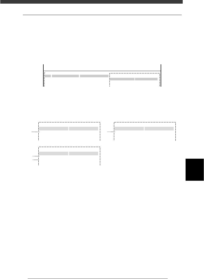
Badmark registration screen (Mark Info. screen)
27625-C0-00
PCB:
Mark Type Info.
Edit Term
OBJ : Mark Info.
MARK NAME
BADMARK
No.
1
2
3
COMMENT
For PCB
:
V
<<<APPLICATION>>> 2/DATA/M
<<MODE>> 1/EDIT_DATA
2 Set the parameters in sub-windows.
While switching the sub-windows by pressing the [F4] key, set the
following parameters.
Badmark parameter settings
27626-C0-00
:
:
Mark Type Info.
Edit Term
Mark Type
DataBase Number
:
:
:
153
Mark size Info.
Edit Term
Search Area 4.00
Vision Info.
Edit Term
Surface Type
Mark Threshold
:
:
:
Reflect
220
Badmark
1
3
4
2
Mark Type Info. parameter
1. Mark Type
Set to “Badmark”.
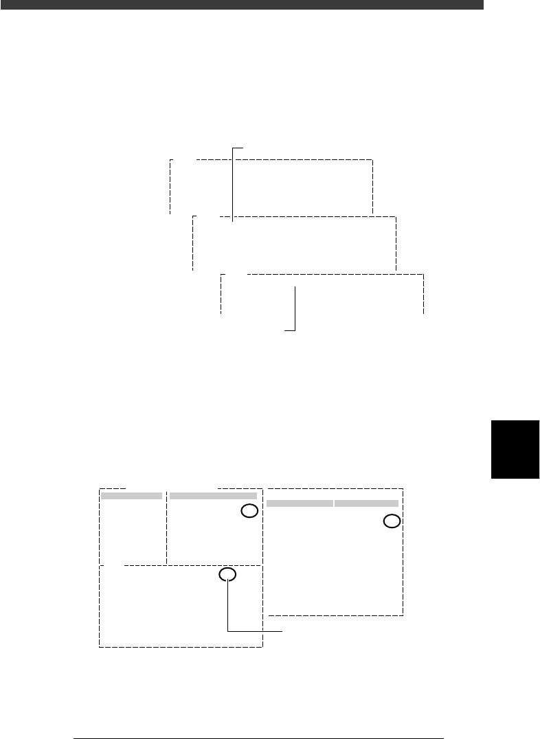
Mark Size Info. parameter
2. Search Area
This parameter specifies the size of an square area in which a mark is
searched. The setting value can be 0.00 to 9.99 (in millimeters) which
represents the length of one side. The larger this value, the larger the
search area.
The search area must be smaller than the badmark to be detected,
because the machine detects the badmark depending on whether it is
reflective or non-reflective within the specified search area.

6
-44
EPD8013110
Operation
Chapter 6
6
Using various functions
6
Mark Search Area setting
23616-C0-00
Search area
Badmark
Enter this length in millimeters.
Vision Info. parameters
3. Surface Type
If the mark is brighter than the PCB, set this parameter to “Reflect”, and
if darker, set to “NonReflect”.
4. MarkThreshold
An optimum value for this parameter is obtained with the Adjust
Assistant (Step 3). Leave the initial setting as it is.
Reference
The badmark function is used only to judge whether a badmark is present on the PCB so
there are no strict conditions with respect to the mark shape and size.
3 Execute the Adjust Assistant.
The Adjust Assistant can be used to find the optimum threshold level for
recognizing a badmark. Before making this adjustment, check that the
Mark Type parameter in the Mark Type Info. sub-window is set to
“Badmark”.
1. Select the mark data on the Mark Info. screen and press the [F6] key (or
execute the <2/1/B1 ADJUST ASSISTANT> command) to open the
Adjust Assistant screen.
Adjust Assistant screen (badmark)
27627-C0-00
Mark Name : BADMARK
Command
FIX PCB
TEACH MARK
VISION TEST
PARAM. SEARCH
*
*
CHK THRESHOLD
EXIT
Adjust Assist Items
Surface Type
Mark Threshold
Mark OutSize (mm)
NonReflect
127
4.00
2. Clamp a PCB on the conveyor.
Use the FIX PCB command to clamp the PCB in place on the conveyor.
3. Execute the PARAM. SEARCH command to find the optimum threshold
for recognizing the mark.
A teaching screen for non-mark area appears when this command is
executed. According to the message displayed on the Adjust Assistant
screen, manipulate the YPU joystick to move the camera so that the
cross cursor on the vision monitor is at a position on the PCB where no
marks or patterns are present.
6
-45
EPD8013110
Operation
Chapter 6
6
Using various functions
4. When the position is selected, press the [ENTER] key.
The threshold level for detecting the area with no mark is entered as
the LEVEL 1 on the Adjust Assistant screen. The message then changes,
asking you to perform teaching at the badmark position. Manipulate the
YPU joystick so that the cross cursor on the vision monitor is aligned
with the badmark affixed on the PCB.
Threshold level teaching screens (for badmark)
27628-C0-00
V196
(LEVEL 1= LEVEL 2= RESULT= )
Please teach badmark as detected. (1st)
Hit [ENTER] to finish teaching.
When you move table or head,
Be careful for safety !!!
V197
(LEVEL 1=20 LEVEL 2= RESULT= )
Please teach badmark as detected. (2nd)
Hit [ENTER] to finish teaching.
When you move table or head,
Be careful for safety !!!
V200
(LEVEL 1= 20 LEVEL 2=118 RESULT= 80 )
PARAM. SEARCH for mark succeeded.
Threshold level when no mark is detecte
d
Threshold level when mark is detected
5. When the badmark is positioned in the center of the vision monitor,
press the [ENTER] key.
The threshold level of the badmark is now measured and entered as the
LEVEL 2. At the same time, the mid value between the LEVEL 1 and
LEVEL 2 is entered as the RESULT value. This value is used as the
optimum threshold level when detecting the badmark.
PARAM. SEARCH command screen (for badmark)
27629-C0-00
Mark Threshold
Vision
Edit Term
Mark Threshold
Info.
V200
(LEVEL1= 20 LEVEL2=118 RESULT= 69 )
PARAM. SEARCH for mark succeeded.
Mark Name: BADMARK
Command Adjust Assistant Items
69
69
:
:
Mid value between LEVEL 1 and
LEVEL 2 is calculated and reflected
on "Mark Threshold" value.