YV180X_Ope_E.pdf - 第134页
5 -58 EPD8013110 Operation Chapter 5 5 Creating the PCB data 3.7 Adjust Assistant commands The Adjust Assistant commands allow you to check whether the parameter settings are correct. While performing the r ecognition te…
5
-57
EPD8008100
Operation
Chapter 5
5
Creating the PCB data
50. Comp. Intensity
51. MultiCam Marker
6. SHAPE INFO. parameters
Set these parameters after specifying the VISION INFO. parameters. If
“Alignment Type” is undefined, the following parameters are not dis-
played.
61. Body Size X, Body Size Y
Enter the correct dimensions including the leads, measured with a vernier
caliper or micrometer.
62. Body Size Z
Enter the correct thickness measured with a vernier caliper or micrometer.
63. Ruler Offset
Refer to the description in “3.4.1 Mini-mold transistors/SOT”.
62. Ruler Width
Refer to the description in “3.4.1 Mini-mold transistors/SOT”.
63. LeadNumber
Enter the number of leads existing on one side in either E or W direction.
64. ReflectLL
Enter the projected length of leads which reflect light during recognition.
Use the default setting in most cases.
65. LeadWidth
Enter the correct lead width.
66. LeadPitch
Enter the correct lead pitch (lead-to-lead spacing).
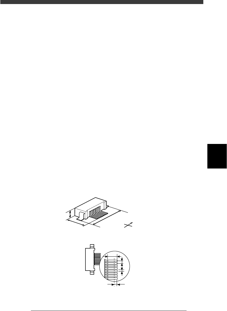
SHAPE INFO. parameters for connectors
23517-C0-00
S
N
W
E
B
C
A
E
F
G
A : Body Size X
B : Body Size Y
C : Body Size Z
D : Ruler Offset
E : Reflect LL
F : LeadPitch
G : LeadWidth
Bottom view
D
5
-58
EPD8013110
Operation
Chapter 5
5
Creating the PCB data
3.7 Adjust Assistant commands
The Adjust Assistant commands allow you to check whether the parameter
settings are correct. While performing the recognition test with the Adjust
Assistant commands, you can also find and determine an optimum value
for parameters which have not yet been set.
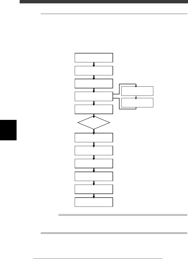
Typical flow chart using the Adjust Assistant commands
23518-C0-00
Select component data
Open Adjust
Assistant screen
Set feeder position
Execute PICK UP COMP.
Execute VISION TEST
Check head & nozzle
to be used
Check pickup/mount
vacuum levels
Execute
DRAW THE SHAPE
Execute PARAM SEARCH
Execute
VISION TEST again
No error
Discard component
Quit Adjust Assistant
ERROR
n
NOTE
The A-table head picks up a component installed in the feeder set positions from No. 1 to
40, while the B-table head picks up a component from the feeder set positions from No.
101 to 140.
5
-59
EPD8013110
Operation
Chapter 5
5
Creating the PCB data
1 Set up the component feeder.
Install the feeder with components you want to check, onto the feeder
plate. Be sure that the feeder set position matches the number previously
set for the Feeder Set No. in the BASIC INFO. sub-window. If the Feeder
Set No. has not yet been determined, you can specify it on the Adjust
Assistant screen, so install the feeder at a position you can easily access.
Reference
To see a list of all the feeder set positions for components registered in the selected PCB
data, select <2/1/C1 EDITOR ASSISTANT>→”COMP. ASSIGNMENT”→”PUT IN
SET_NO” and press the [ENTER] key.
2 Select the component data.
On the Component Info. screen, move the cursor to the component data
you want to check.
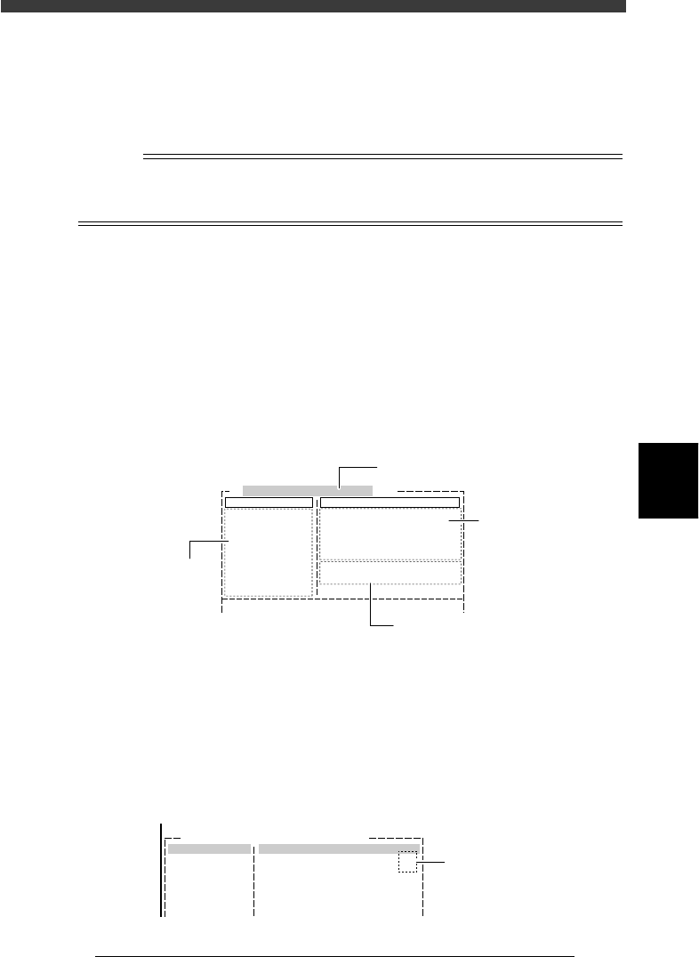
3 Open the Adjust Assistant screen.
Press the [F6] key or run the <2/1/B1 ADJUST ASSISTANT> command. The
Adjust Assistant screen then appears. This screen consists of the Command
window showing various commands used during adjustment and the
Adjust Assist Items window showing component parameters as shown
below.
Adjust Assistant screen
27522-D8-00
Comp. Name : R1005
Command
PICK UP COMP.
*
VISION TEST
PARM. SEARCH
DISCARD COMP.
DRAW THE SHAPE
CHK GRAY VALUE
EXIT
Adjust Assist Items
Feeder set No.
Comp. Tolerance
Comp. Threshold
Lighting Level
Search Area
Monitor Mode
Condition Chk.Mode
20
30
30
9.00
Nothing
ROW
(%)
(mm)
6 / 8
Selected component name
Adjust Assistant
commands
Vision display status
Parameters in
Component Info.
4 Enter the feeder set number.
Enter this parameter only for components whose feeder position is
unspecified. Press the right arrow key to move the cursor to “Feeder Set
No.” in the Adjust Assist Items window, then enter the number of the
feeder plate position at which the feeder is installed. When a feeder set
No. larger than “101” is specified, the B-table head assembly will pick up
the component.
Feeder position input screen
27523-C0-00
Comp.Name:
Command
Adjust Assistant Items
Feeder Set No.
20
Enter feeder set
number here