YV180X_Ope_E.pdf - 第137页
5 -61 EPD8013110 Operation Chapter 5 5 Creating the PCB data 8 Check and adjust the reference pickup/mount vacuum levels. T o check the reference vacuum levels used to determine whether or not a component is being picked…
5
-60
EPD8013110
Operation
Chapter 5
5
Creating the PCB data
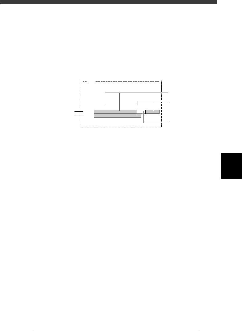
5 Run the PICK UP COMP. command.
Press the left arrow key to move the cursor back to the PICK UP COMP.
command and press the [ENTER] key. The head and nozzle check screen
then appears.
PICK UP COMP. command
27524-C0-00
Comp.Name : QFP208-P0.50
Command
PICK UP COMP.
Adjust Assistant Items
Move the cursor here and press the [ENTER] key.
6 Check the head and nozzle to be used.
The head number and nozzle type to be used are shown on the screen.
Press the [ENTER] key to dvance to the next step when the display is okay.
To change the head number, press the [Space], [INS] or [DEL] key. If you
want to change the nozzle type, select the EXIT command to return to the
Component Info. edit screen, then change the “Required Nozzle” setting
in the BASIC INFO. sub-window.
Head and nozzle check screen
27525-C0-00
V120
Please specify number of head to pick
up a component.
Required type of nozzle is
TYPE-72
HEAD NO. : 1
If you want to change the nozzle type,
change the “Required Nozzle” setting
in the BASIC INFO. sub-window.
To change the head No.
press the [Space], [INS] or [DEL] key.
7 Press the [ENTER] key to perform component pickup.
The head assembly moves to pick up a component, and the pickup and
mount vacuum levels are displayed on the message display area.
Reference
If the component could not be picked up, refer to “10.3.3 Pickup errors” in this chapter.
5
-61
EPD8013110
Operation
Chapter 5
5
Creating the PCB data
8 Check and adjust the reference pickup/mount vacuum
levels.
To check the reference vacuum levels used to determine whether or not a
component is being picked up by a nozzle, follow these steps.
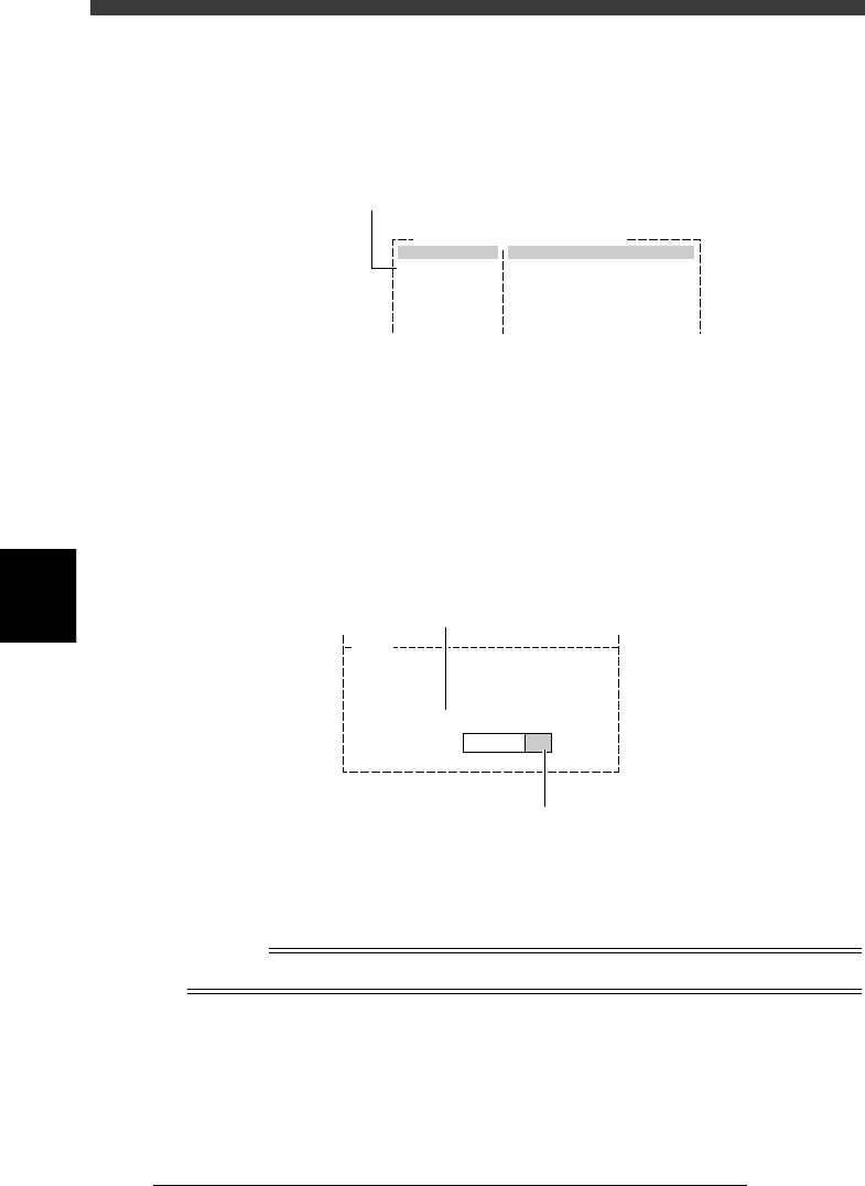
1. Look at the pickup and mount vacuum pressure levels shown on the
message display area of the Adjust Assistant screen during component
pickup. The reference vacuum levels and actual vacuum levels are
graphically displayed as green and white bars as shown below.
Pickup and mount vacuum pressure levels
27526-C0-00
V161
Upper bar: settings. Lower bar: current level.....
.....................
.....................................................................................
...................................................................
PICK 30%, MNT 30% (SHIFT).
DATA
LEVEL
C
D
E
A
B
A: DATA bar (upper bar graph)
Shows the reference pickup and mount vacuum level settings in green
and white.
B: LEVEL bar (lower bar graph)
Shows the actual vacuum level currently being measured. The bar
moves to the right as the vacuum level increases.
C: Left-hand green bar
Represents the reference pickup vacuum level setting. The setting value
is indicated in percent (PICK %) just above the bar graph. This green
bar moves to the right as the reference pickup vacuum level setting
increases. Use the [INS] or [DEL] key to make adjustment.
D: Right-hand green bar
Represents the reference mount vacuum level setting. The setting value
is indicated in percent (MNT %) just above the bar graph. This green
bar moves to the left as the reference mount vacuum level setting
increases. Use the [SHIFT]+[INS] or [SHIFT]+[DEL] key to make
adjustment.
E: White zone
If the white bar zone becomes too narrow (reference pickup vacuum
level + mount vacuum level setting exceeds 100%), the entire bar
graph turns red indicating the settings are not appropriate. In this case,
press the [DEL] or [SHIFT]+[DEL] keys until the green bars and white
zone reappear.
5
-62
EPD8013110
Operation
Chapter 5
5
Creating the PCB data
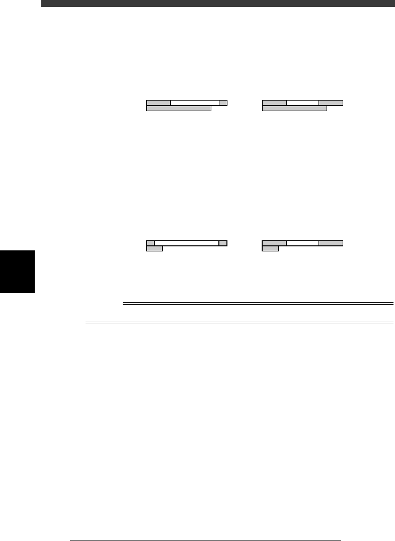
2. Check the reference mount vacuum level.
Check that the LEVEL bar overlaps with the right-hand green area on
the DATA bar. If not, increase the reference mount vacuum level (MNT)
with the [SHIFT]+[INS] keys.
Adjusting the reference mount vacuum level
23519-C0-00
DATA
LEVEL
PICK30%, MNT10%(SHIFT).
DATA
LEVEL
PICK30%, MNT30%(SHIFT).
NG OK
e
3. Check the reference pickup vacuum level.
Press the emergency stop button, then remove by hand the component
being picked up. Now check that the LEVEL bar is within the left-hand
green area on the DATA bar. If the LEVEL bar exceeds the green area
and overlaps with the white area, adjust the reference pickup vacuum
level (PICK) with the [INS] key. After having adjusted it, cancel the
emergency stop button and press the [READY] button.
Adjusting the reference pickup vacuum level
23520-C0-00
DATA
LEVEL
PICK10%, MNT30%(SHIFT).
DATA
LEVEL
PICK30%, MNT30%(SHIFT).
NG OK
4. Run the PICKUP COMP. command to pick up the component again
when the checks and adjustments are complete.
Reference
Refer to “3.9 Pickup and mount vacuum pressures” in this chapter for more details.
9 Run the VISION TEST command.
This command checks whether the component is correctly recognized
with the camera. Move the cursor to the VISION TEST command and press
the [ENTER] key. Perform this test several times. If no error is detected,
each parameter is appropriate so advance to the next step. If an error
occurs during this test, make adjustments with the procedure below.
1. Run the DRAW THE SHAPE command.
After checking the direction of the component displayed on the vision
monitor, run the DRAW THE SHAPE command. An outline of the
component is displayed on the vision monitor, based on the setting
data defined in the component information, so confirm whether it
matches the component image you have checked with the VISION
TEST command. If the direction does not match, quit the Adjust
Assistant once, then correct the “Pick Angle deg” parameter setting in
the PICK & MOUNT sub-window.