YV180X_Ope_E.pdf - 第94页
5 -18 EPD8008100 Operation Chapter 5 5 Creating the PCB data Feeder T ype settings (when “ Comp. Pac kage ” is set to “ Bulk ” ) 25502-C0-00 Bulk-1005C Bulk-1005R * Bulk-1608C Bulk-1608R * Bulk-T0.6C Bulk-T0.6R Bulk-T1.2…
5
-17
EPD8008100
Operation
Chapter 5
5
Creating the PCB data
1. BASIC INFO. parameters
1. Comp. Package
Select the type of component feed.
• Tape
Select this setting when using a tape feeder which supplies compo-
nents on paper tape, embossed tape or adhesive tape.
• Stick
Select this setting when using a stick feeder such as a single stick
feeder, multi-stick feeder, staked stick feeder and high-speed stick
feeder.
• Bulk
Select this setting when using a bulk cassette feeder.
2. Feeder Type
Select the specific feeder type to be used for component supply. Selectable
items differ depending on the Comp. Package setting. Refer to the table
below to make a selection.
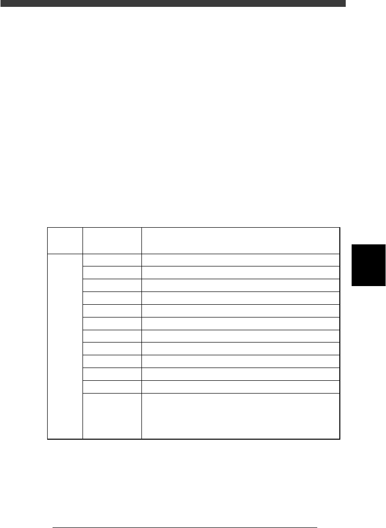
Feeder Type settings (when “Comp. Package” is set to “Tape”)
25501-C0-00
8mm tape feeder (except for 1005 chip)
8mm tape feeder (except for 0603 chip)
8mm tape feeder (for 1005 chip)
12mm tape feeder (standard pitch)
12mm tape feeder (long pitch)
16mm tape feeder
24mm tape feeder
32mm air-driven feeder with sticky tape
32mm embossed air-driven feeder
44mm embossed air-driven feeder
56mm embossed air-driven feeder
8mmTape
8mm 0603cmp
8mm1005cmp
12mmEmboss
12mmLongPitch
16mmEmboss
24mmEmboss
32mmSticky
32mmEmboss
44mmEmboss
56mmEmboss
Tape-A to D
Select these settings when using a tape feeder other than
the above. Note that you must make necessary settings on
the <3/1/B4 FEEDER SPEC. INF> screen.
For the setting procedure, refer to the mounter service
manual.
Comp.
Package
setting
Feeder Type
setting
Tape feeder or bulk cassette feeder type
Tape
5
-18
EPD8008100
Operation
Chapter 5
5
Creating the PCB data
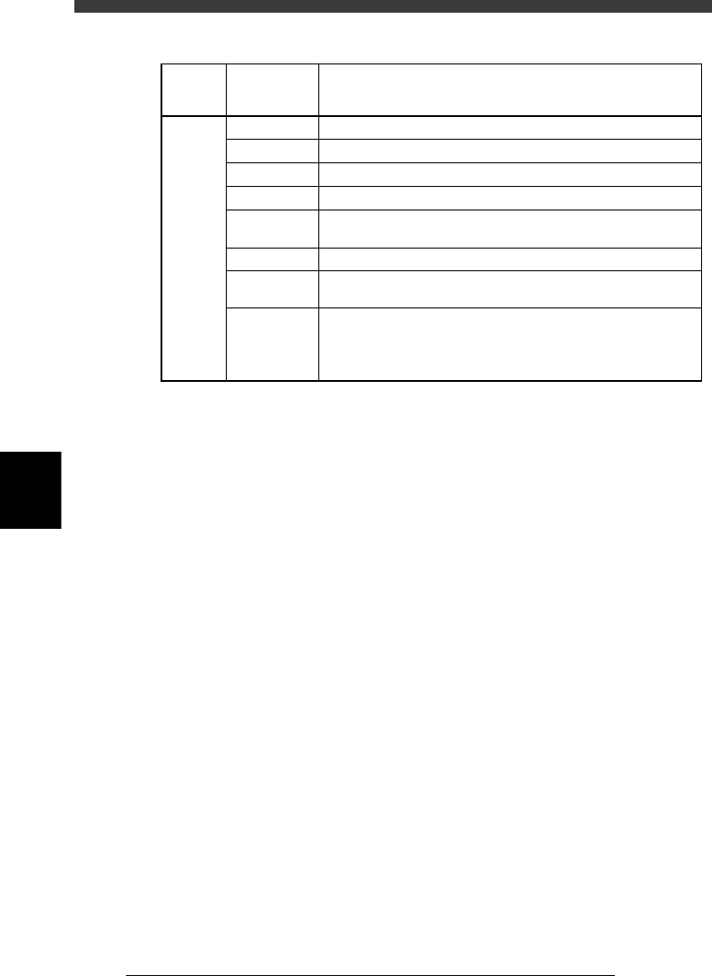
Feeder Type settings (when “Comp. Package” is set to “Bulk”)
25502-C0-00
Bulk-1005C
Bulk-1005R *
Bulk-1608C
Bulk-1608R *
Bulk-T0.6C
Bulk-T0.6R
Bulk-T1.25C
Bulk-A to D Select these settings when using a bulk feeder other than the
above. Note that you must make necessary settings on the
<3/1/B4 FEEDER SPEC. INF> screen.
For the setting procedure, refer to the mounter service manual.
Bulk feeder for 2125 capacitors (chip thickness 1.25mm). Marked
"2125 T1.25" on the feeder.
Bulk feeder for 2125 resistors. Marked "2125 T0.6" on the feeder.
Bulk feeder for 2125 capacitors (chip thickness 0.6mm). Marked
"2125 T0.6" on the feeder.
Bulk feeder for 1608 resistors. Marked "1608 R" on the feeder.
Bulk feeder for 1608 capacitors. Marked "1608 C" on the feeder.
Bulk feeder for 1005 resistors. Marked "1005 R" on the feeder.
Bulk feeder for 1005 capacitors. Marked "1005 C" on the feeder.
Comp.
Package
setting
Bulk
Feeder Type
setting
Tape feeder or bulk cassette feeder type
3. Required Nozzle
Select the optimum nozzle that matches the component size from among
the nozzle types for chip components. (See “Nozzle table” listed in the
supplement in this manual.)
4. Feeder Set No.
Enter the feeder set number of the position at which the feeder is installed.
This parameter setting is unnecessary when the Use feeder opt. parameter
is set to “Yes.”
5. Pos. Definition
Set to “Automatic” when you set the Comp. Package parameter to “Tape”
or “Bulk”. (The pickup position is automatically calculated.)
6. Feeder Pos_X
This parameter is skipped when the Pos. Definition parameter is set to
“Automatic”.
2. OPTION INFO. parameters
Some of these parameters are displayed only when the Simple Edition
parameter on the <3/1/A1 OPTION CONFIG.> screen is set to “Full
Items”.
11. FixCmpRef.
Set this parameter to “0” in normal operation. Enter static component
numbers here only when used. See “4. Static component information” in
Chapter 6 for more details.
12. Alt. Cmp.
This parameter specifies an alternative component number which can be
used if the current component runs out. When not needed to specify any
alternative component, leave it at “0”. For detailed information about
5
-19
EPD8008100
Operation
Chapter 5
5
Creating the PCB data
specifying an alternative component, see “8. Alternative components” in
Chapter 6.
13. Use feeder opt.
Set to “Yes” when you want to change the feeder set positions according to
results obtained with the DATA GENERATOR commands. (See “9. Data
optimization” in this chapter.) Set to “No” if you do not want to change
these positions. Setting to “Yes” is advised.
14. Comp. Group No.
When a nozzle lowers to mount a low-profile component after tall
components have been mounted on the PCB, the neighboring nozzles may
interfere with those tall components. To avoid this, components can be
grouped by height so that they are mounted in the desired order (0 to 99).
When no mounting order is needed, set this parameter to “0”.
15. Correct Pickpos.
Set this parameter to “NotUse” in normal operation.
3. PICK & MOUNT INFO. parameters
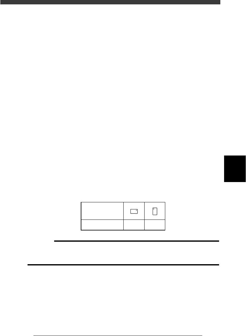
21. Pick Angle deg
This parameter specifies the angle through which the mounter head rotates
to pick up a component on the feeder. This setting determines the orienta-
tion of the component (recognition reference) when it is recognized and
displayed on the vision monitor. Normally, set this parameter to 0° for
horizontally long components in the loading position on the feeder, and set
to 90° for vertically long components. When you are using a bulk cassette
feeder, always set this parameter to 90°.
Chip component pickup angle
25503-C0-00
0 deg. 90 deg.
Loading position
Pickup angle
NS
E
W
N
S
WE
c
CAUTION
Pickup angle setting directly affects the recognition reference and mounting angle. Be
careful not to mistake 0° for 180° for horizontally long components in the loading
position and 90° for -90° for vertically long components.
22. Pick Timer, Mount Timer
These parameters specify the time duration (in seconds) for which the head
stays in the lowered position after detecting the reference pickup or mount
vacuum pressure when picking up or mounting a component. For small