YV180X_Ope_E.pdf - 第292页
6 -57 EPD8013110 Operation Chapter 6 6 Using various functions 9. Patter n matching Pattern matching is a function for correcting PCB dimensional or reference hole errors, positioning errors occurring from the PCB clampi…
6
-56
EPD8013110
Operation
Chapter 6
6
Using various functions
6
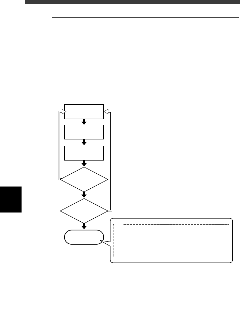
8.4 Component switching flow
In the Alternative component function, component feed is switched in the
operation flow explained below.
When the components in the current feeder run out, the machine allows
automatic switching to the alternative component feeder without interrupt-
ing operation. When one cycle using alternative components is complete,
the machine stops and a message asking you to resupply the components
then appears. In the case of components supplied from a nonstop feeder
system (option), the machine can continue operation by resupplying the
components during operation.
Operation flow
23620-C0-00
Out of components
Automatic operation
NO
YES
YES
NO
Machine stops
E87
NO COMPONENT FOR USE
All components in alternative loop are not available.
This can be caused by the following:
-Pick up or recognition error happened.
-Component counter reached specified number.
Refill the components or check feeders and run again.
Automatically switches
to alternative
components
Is one cycle using
alternative component
group complete?
Were components
resupplied during
operation?
6
-57
EPD8013110
Operation
Chapter 6
6
Using various functions
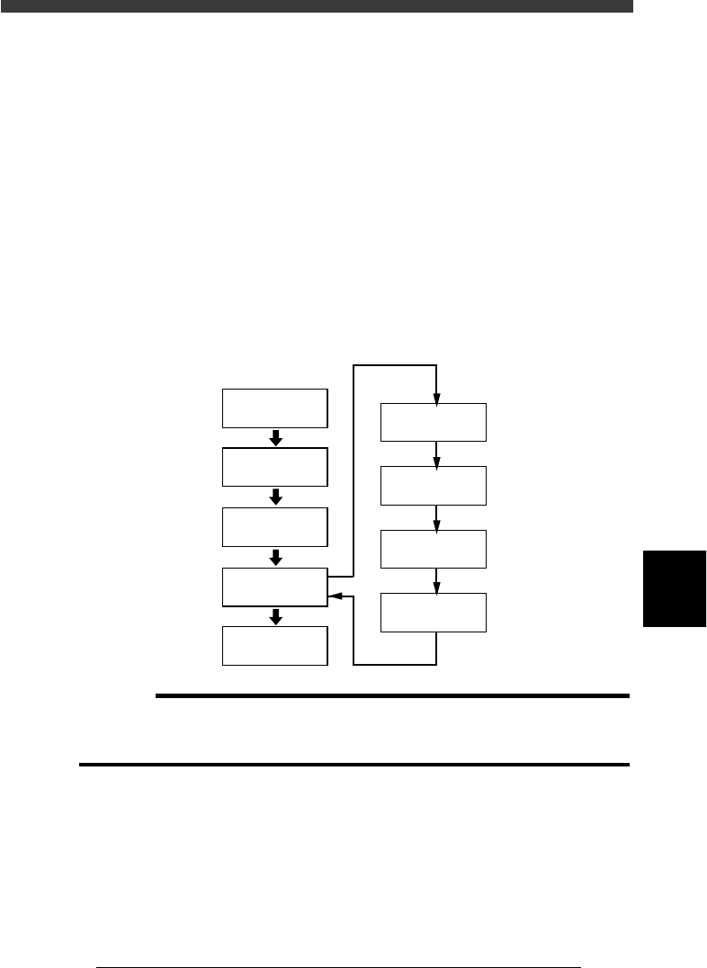
9. Pattern matching
Pattern matching is a function for correcting PCB dimensional or reference
hole errors, positioning errors occurring from the PCB clamping mecha-
nism, or local distortion of the PCB. To use this function, the image of a
particular PCB pattern must be registered as the template. Errors or
distortion are corrected by comparing the template you registered with an
actual pattern being recognized. Pattern matching is useful when the
fiducial function cannot be used, for example, if the PCB has no fiducial
marks or the mark does not match any mark recommended by YAMAHA.
Any shape of pattern can be used, but the pattern image should be smaller
than about 1/4th of the monitor. Pattern matching accuracy may drops
slightly compared to cases in which round or square marks are used.
Pattern matching
23621-C0-00
Open Mark Info.
Excute Adjust
Assistant
Save data
Secure the PCB
in place
Save Pattern
Check Pattern
display
Execute
VISION TEST
Set Algorithm
Type to “Pattern”
Register
Pattern Data
c
CAUTION
Pattern matching requires a longer recognition time than normal mark recognition. It is
not necessary to use pattern matching for marks which can be correctly recognized with
the Algorithm Type parameter in the Vision Info. sub-window set to “Normal”.
6
-58
EPD8013110
Operation
Chapter 6
6
Using various functions
6
9.1 Pattern registration
To utilize pattern matching, you must register the reference pattern in the
template.
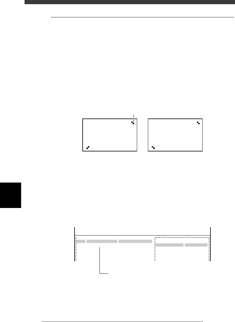
1 Decide on the pattern.
Decide which pattern you want to use for pattern matching. Select a pair
of patterns that meet the following conditions.
• Each pattern clearly contrasts with the PCB. (It is okay if the outline of
each pattern is definite.)
• A pair of patterns are diagonally opposing on the PCB. (The same point
cannot be used.)
• Each pattern should have the same shape and face the same direction.
Pattern conditions
23622-C0-00
Pattern
NG OK
2 Register the pattern data in the mark information.
1. In the <2/1/EDIT_DATA> mode, select “Mark Info.” from the edit object
list and press the [ENTER] key.
(When you are editing other information, pressing the [F3] key displays
the edit item list.)
2. Move the cursor to the No. for registering the data and enter a name in
the “MARK NAME” column to allow identification of this pattern.
Mark Info. screen
27636-C0-00
PCB :
No.
1
2
3
MARK NAME COMMENT
Mark Type Info.
Edit Term :
OBJ :Mark Info.
<<<APPLICATION>>>
<<MODE>>1/EDIT_DATA
2/DATA/M
Mark Type
Database Number
Enter the mark name to be recognized as a pattern.