YV180X_Ope_E.pdf - 第175页
5 -99 EPD8013110 Operation Chapter 5 5 Creating the PCB data 6.2.3 Setting the PCB origin for multi-block PCB In the case of multi-block PCBs, the PCB origin should be set to the same position as the block repeat positio…
5
-98
EPD8013110
Operation
Chapter 5
5
Creating the PCB data
6.2.2 Setting the PCB origin at a position other
than the locate pin
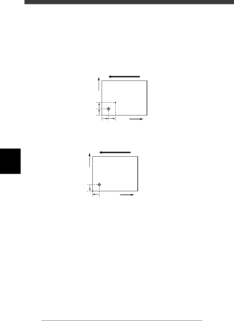
When setting the PCB origin at a position other than the locate pin as
shown below, enter the XY coordinates relative to the locate pin position in
the “X/X1” and “Y/Y1” columns of the PCB Origin parameter.
Setting the PCB origin at a position other than the locate pin
23543-C0-00
5mm
5mm
5mm5mm
X
Y
Direction of PCB flow
When setting the PCB
origin at point A, enter
“X=5.00” and Y=5.00.
A
Setting the PCB origin at the corner of the PCB
23544-C0-00
5mm
5mm
X
Y
Direction of PCB flow
When setting the PCB origin at
the corner of a PCB in right-to-
left flow (with the front rail fixed),
enter “X=-5.00” and Y=-5.00.
5
-99
EPD8013110
Operation
Chapter 5
5
Creating the PCB data
6.2.3 Setting the PCB origin for multi-block PCB
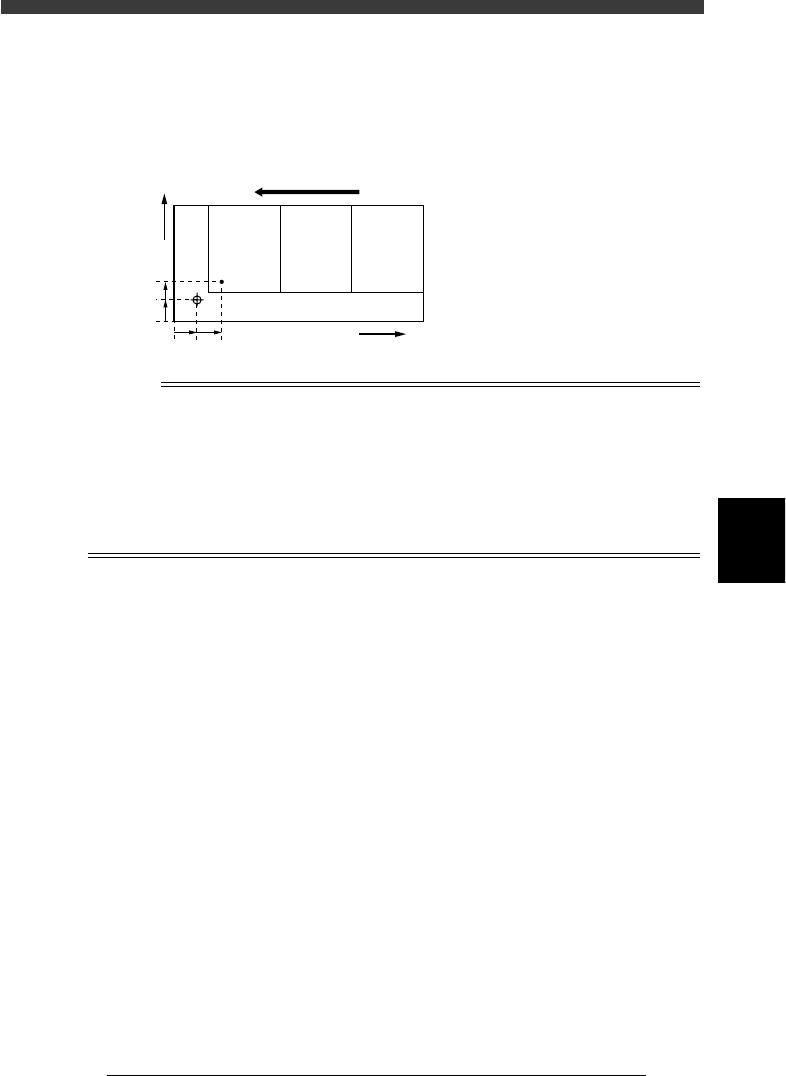
In the case of multi-block PCBs, the PCB origin should be set to the same
position as the block repeat position of the 1st block.
PCB origin position for multi-block PCB
23545-C0-00
5mm
3mm
5mm 5mm
X
Y
No.1 No.2 No.3
Direction of PCB flow
When setting the PCB origin at the
block repeat point in the 1st block
in right-to-left flow as shown at left,
enter “X=5.00” and Y=3.00.
Reference
If you are not sure the correct coordinates of the PCB origin, the following procedure will
prove convenient.
1. Set the teaching conditions by selecting the teaching table (A or B table), “Camera” as
the teaching unit and “NotUse” for fiducial correction.
2. Manipulate the YPU joystick to move the camera so that the center of the
PCB origin is positioned in the center of the vision monitor.
3. When the position is determined, press the [F10] key, and the teaching
position is now entered.
5
-100
EPD8013110
Operation
Chapter 5
5
Creating the PCB data
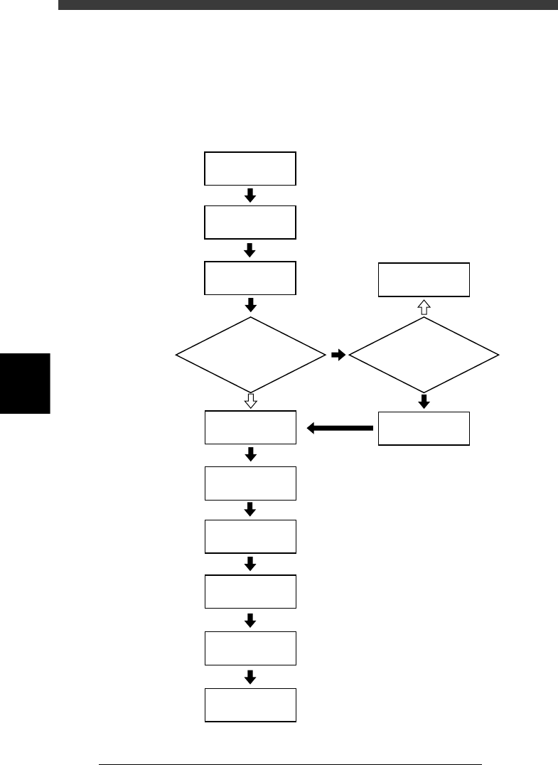
7. Creating the mount information
The mount information specifies the data on mounting position coordi-
nates, component numbers to be mounted and other information related to
mounting.
Flow chart for creating the mount information
23546-C0-00
Enter
land pattern name
Open Mount Info.
Enter
component number
Teach
mounting position
Enter XY data
Enter R data
Check head No.
Set fiducial mark
Chapter 6
☞
5
☞
Enter XY data
by teaching?
Is PCB clamped?
Set badmark
Set to "Exec"
Clamp PCB
YES
NO
YES
NO
Chapter 6
☞
7.3
☞