YV180X_Ope_E.pdf - 第112页
5 -36 EPD8008100 Operation Chapter 5 5 Creating the PCB data 6. SHAPE INFO. parameters Set these parameters after specifying the VISION INFO. parameters. If “ Alignment T ype ” is undefined, the follo wing par ameters ar…

5
-35
EPD8008100
Operation
Chapter 5
5
Creating the PCB data
23. Pick Height, Mount Height
Refer to the description in “3.3.1 Standard chip components”.
24. Pick Sequence
Refer to the description in “3.3.1 Standard chip components”.
25. Mount Action
This specifies the nozzle descent movements during component mounting.
Set this parameter to “Normal” in most cases.
26. Vacuum Check
Refer to the description in “3.3.1 Standard chip components”.
27. Pick Vacuum, Mount Vacuum
These are reference vacuum pressures used for checking the pickup and
mount vacuum levels. Use the default settings and adjust them as needed
in the Adjust Assistant mode. (See “3.7” in this chapter.)
28. Conv. Y Speed
Refer to the description in “3.3.1 Standard chip components”.
4. DUMP INFO. parameters
31. Dump Way
Set to “Dump POS” (discard point). See the mounter service manual for
details on the discard point.
32. Retry Times
Refer to the description in “3.3.1 Standard chip components”.
5. VISION INFO. parameters
41. Alignment Group
Set this parameter to “IC”.
42. Alignment Type
Set this parameter to “SOP”.
43. AlignmentModule
This parameter specifies the lighting method for recognizing a component.
Use the default setting (Fore&Back&Laser) in most cases. Refer to the
description in “3.3.1” for more details.
For descriptions of the following VISION INFO. parameters, refer to
“3.3.1 Standard chip components”.
44. Light Selection
45. Lighting Level
46. Comp. Threshold
47. Comp. Tolerance
48. Search Area
49. Datum Angle
50. Comp. Intensity
51. MultiCam. Marker
5
-36
EPD8008100
Operation
Chapter 5
5
Creating the PCB data
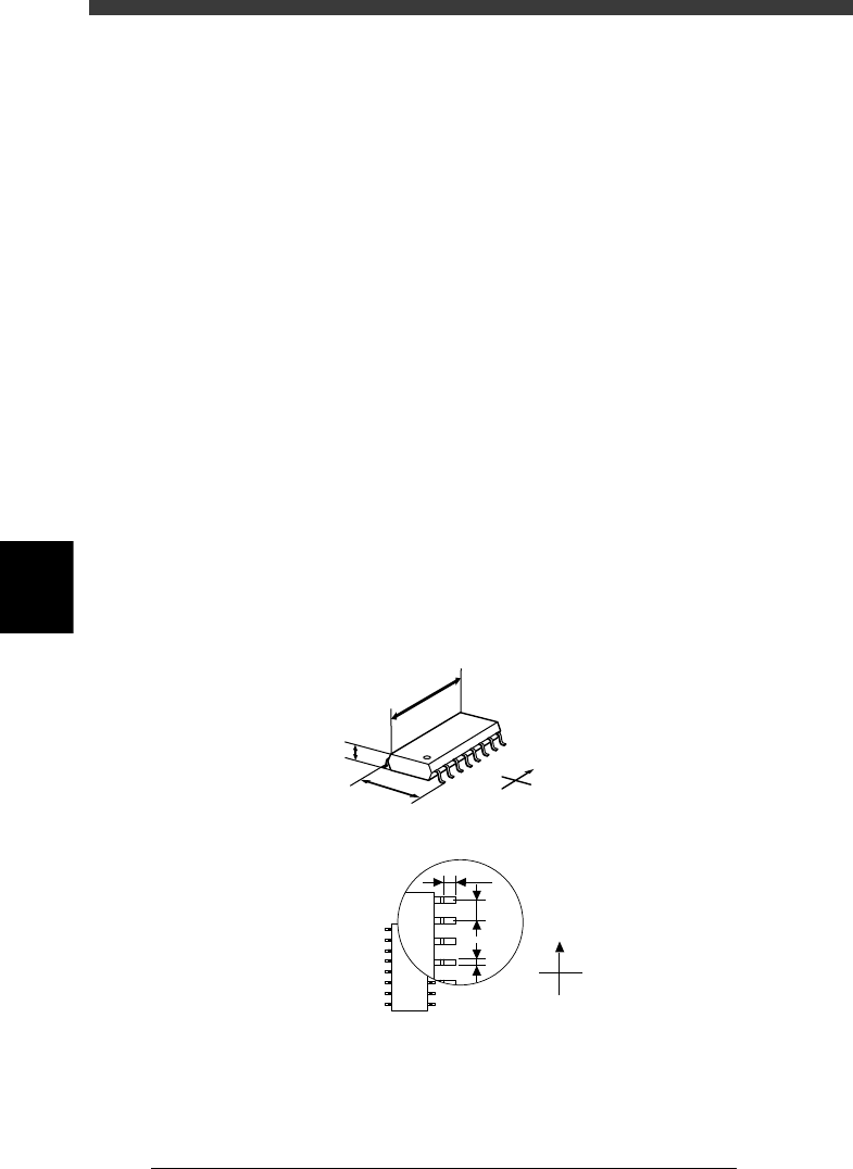
6. SHAPE INFO. parameters
Set these parameters after specifying the VISION INFO. parameters. If
“Alignment Type” is undefined, the following parameters are not dis-
played.
61. Body Size X, Body Size Y
Enter the correct dimensions including the leads, measured with a vernier
caliper or micrometer.
62. Body Size Z
Enter the correct thickness measured with a vernier caliper or micrometer.
63. Ruler Offset
Refer to the description in “3.4.1 Mini-mold transistors/SOT”.
64. Ruler Width
Refer to the description in “3.4.1 Mini-mold transistors/SOT”.
65. LeadNumber
Enter the number of leads existing on one side in either E or W direction
66. ReflectLL
Enter the projected length of leads which reflect light during recognition.
Use the default setting in most cases.
67. LeadWidth
Enter the correct lead width.
68. LeadPitch
Enter the correct lead pitch (lead-to-lead spacing).
SHAPE INFO. parameters for SOP components
23513-C0-00
N
S
E
W
B
C
A
A : Body Size X
B : Body Size Y
C : Body Size Z
D : Reflect LL
E : LeadPitch
F : LeadWidth
Bottom view
N
S
W
E
D
E
F
5
-37
EPD8008100
Operation
Chapter 5
5
Creating the PCB data
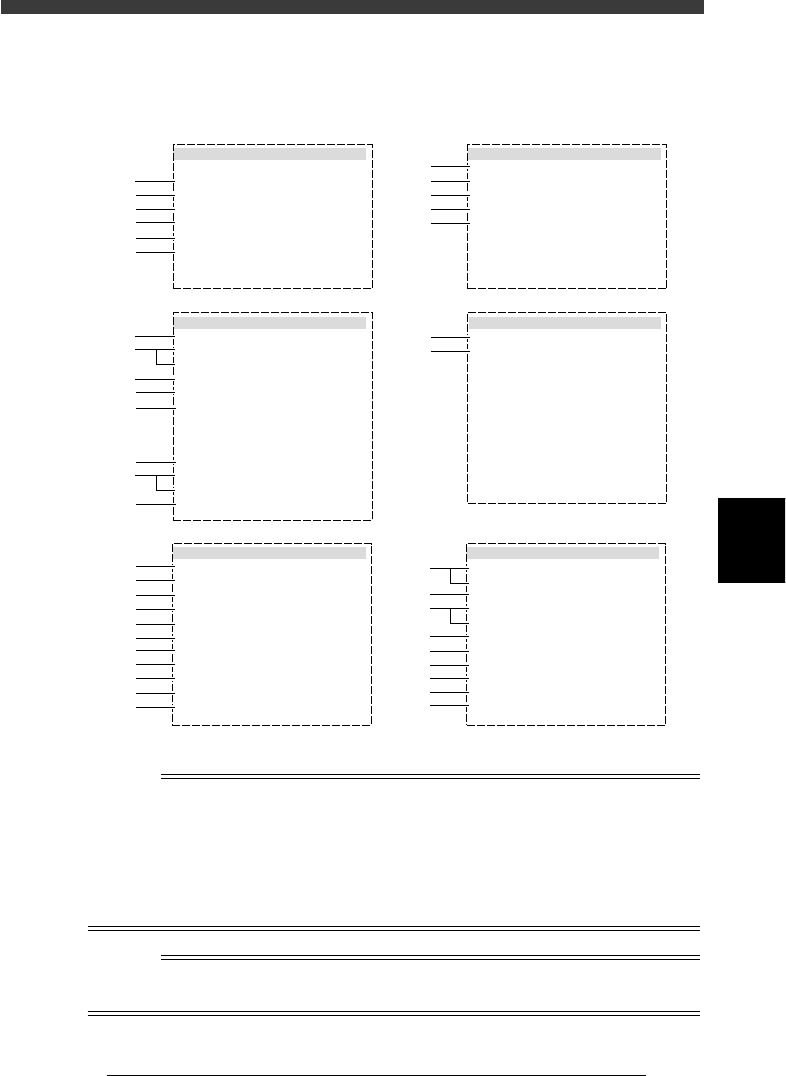
3.4.3 QFP components
QFP components are registered with the parameters shown below.
QFP component parameters
27514-D8-00
6. SHAPE INFO.
Body Size X
Body Size Y
Body Size Z
Ruler Offset
Ruler Width
Lead Number
Lead Number
ReflectLL
LeadWidth
LeadPitch
Bumper Mask
:
:
:
:
:
:
:
:
:
:
:
18.70
24.70
2.90
3
2
20
30
1.20
0.30
0.65
5. VISION INFO.
Alignment Group
Alignment Type
AlignmentModule
Light Selection
Lighting Level
Comp. Threshold
Comp. Tolerance
Search Area mm
Datum Angle
Comp. Intensity
MulriCam. Marker
:
:
:
:
:
:
:
:
:
:
:
IC
QFP
Fore&Back
Main + Coax
6/8
Normal
NotUse
35
30
5.00
0
1 .BASIC INFO.
Database No.
Comp. Package
Feeder Type
Required Nozzle
Feeder Set No.
Pos. Definition
Feeder Pos_X mm
:
:
:
:
:
:
:
Tape
44mmEmboss
ForQFP20mm74
Teaching
767
5
-48.00
2 .OPTION INFO.
FixCmpRef.
AIt.Cmp
Use feeder opt.
Comp. Group No.
Correct Pickpos
:
:
:
:
:
Yes
Not Use
0
0
0
3. PICK AND MOUNT INFO.
Pick Angle deg
Pick Timer
Mount Timer
Mnt Height
Pick Sequence
Mount Action
Mount Speed
PickupSpeed
XY Speed
Vacuum Check
Pick Vacuum
Mount Vacuum
Conv. Y Speed
:
:
:
:
:
:
:
:
:
:
:
:
:
4. DUMP INFO.
Dump Way
Retry Times
:
:
Dump POS
2
s
s
mm
%
%
%
%
%
0
0.30
0.20
Normal
QFP
30
100
100
SPECIAL CHK
FAST
0.2
10
10
mm
mm
mm
N
E
mm
mm
mm
mm
0.00
1
2
3
4
5
6
41
42
43
44
45
46
47
48
49
50
51
11
12
13
14
15
31
32
61
62
63
64
64
65
66
67
68
21
22
23
24
25
26
27
28
n
NOTE
When setting the parameters shown in the sub-windows above, use the number keys to set
the parameters aligned on the right, while using the [INS], [DEL] or [Space] key to set
the parameters aligned on the left. However, there are some parameters which should be
set or optimized with the Adjust Assistant commands described later in “3.7” in this
chapter.
The displayed parameters differ slightly depending on the <3/1/A1 OPTION CONFIG>
settings.
Reference
For QFP size that can be recognized and mounted with the YV100XT, refer to “2.4
Mountable component size” in Chapter 2.