YV180X_Ope_E.pdf - 第54页
4 -15 EPD8013110 Operation Chapter 4 4 Daily operation 3 Select <1/1/D4 ASSIST ANT UTILITY> and press the [EN- TER] key . The ASSIST ANT UTILITY menu box then appears, so select the commands to check or adjust the …
4
-14
EPD8013110
Operation
Chapter 4
4
Daily operation
4
1
Select <1/1/RUNNING> and press the [ENTER] key.
A PCB name selection box is displayed when you have not yet selected a
PCB name.
2
Select the PCB name and press the [ENTER] key.
1. Press the [F2] key (or execute <1/1/E1 SWITCH PCB>) when the list of
PCB names is not directly displayed.
2. Select the PCB name for production and press the [ENTER] key.
The machine then loads the selected PCB data.
3. When you select PCB data which uses bulk feeder components, the
message “Now machine will set BULK component to the top of the
feeder guide” appears. Press the [SPACE] bar to allow setting the bulk
components to the top of feeder guide when the bulk feeder is already
installed on the feeder plate. If not yet installed, press a key other than
the [SPACE] bar.
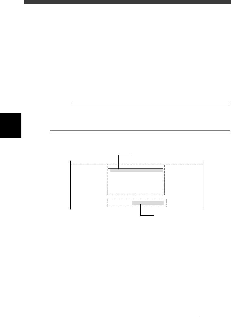
Reference
On the screen showing the PCB name selection box, you can select the PCB name by
typing its first few letters from the keyboard, into the INPUT PCB box which appears upon
typing the first letter of the PCB name. At the same time, the cursor in the PCB name
selection box moves to a PCB name that matches the letters you typed.
INPUT PCB box
27405-C0-00
pcb name
CUK_92001_1
TCO1M2
TCO1M1
TCO1M1_P
1997-03-08
1997-03-22
1997-03-22
1997-03-25
Search PCB : CUK
Cursor moves as you type the PCB name.
Type the PCB name here.

4
-15
EPD8013110
Operation
Chapter 4
4
Daily operation
3
Select <1/1/D4 ASSISTANT UTILITY> and press the [EN-
TER] key.
The ASSISTANT UTILITY menu box then appears, so select the commands
to check or adjust the necessary items.
w
WARNING
BEFORE CHECKING OR ADJUSTING EACH ITEM, ALWAYS PRESS THE
EMERGENCY STOP BUTTON.
CONVEYOR UNITS
Use this utility to change the conveyor unit setups. Select this only
when you have switched the production PCB (in other words, only
when you have selected PCB data which is different from the PCB data
previously selected). See “8. Changing the conveyor unit setup” in this
chapter for more details.
COMPONENT ASSIGNMENT
This utility lists the feeder types and components to be mounted, so
check whether the necessary feeders are installed in the correct feeder
set positions on the feeder plate. For more details on changing the
feeder setups, refer to the separate feeder user’s manual or tray changer
user’s manual.
REQUIRED NOZZLE
This utility shows the nozzle type that can be attached to each head
only when your machine has no nozzle station or uses a head which is
not designed for auto nozzle change. Referring to the display, check
that the correct nozzle is attached to each head. Flying nozzle change
can be performed for heads showing the nozzle number (Nzl.) set to
“0”.
EDIT TRAY COUNTER
This utility can be selected only when a tray changer or tray feeder is
used. (Invalid for the YV180X)
EDIT PRD. HISTORY
Use this utility to reset the production history data or production PCB
counter, or change the maximum number of production PCBs.
FEED BULK COMPONENT
This utility feeds bulk components to the top of a bulk feeder guide.
Use this command when a bulk feeder is used and the bulk compo-
nents have not been set to the top of the feeder guide (see Step 2). In
this case, the bulk feeder must be installed in the correct feeder set
position.
CHECK NOZZLE CONDITION
The machine checks the nozzle tip conditions with the multi-vision
camera. If any error is found, clean the nozzle tip, then execute this
command again to recheck the nozzle tip conditions.
RETURN
Exits the ASSISTANT UTILITY and returns to the previous menu
window.
4
-16
EPD8013110
Operation
Chapter 4
4
Daily operation
4
4
Select the operation speed.
The currently selected speed is displayed in the CONDITION monitor at
the left of the screen. If you want to change this speed, proceed as follows.
1. Press the [SPEED] key on the YPU (or execute “RUNNING SPEED” in
<1/1/ D6 RUNNING UTILITY>).
The 5-step speed selection box then appears.
2. Line up the cursor with the desired speed and press the [ENTER] key.
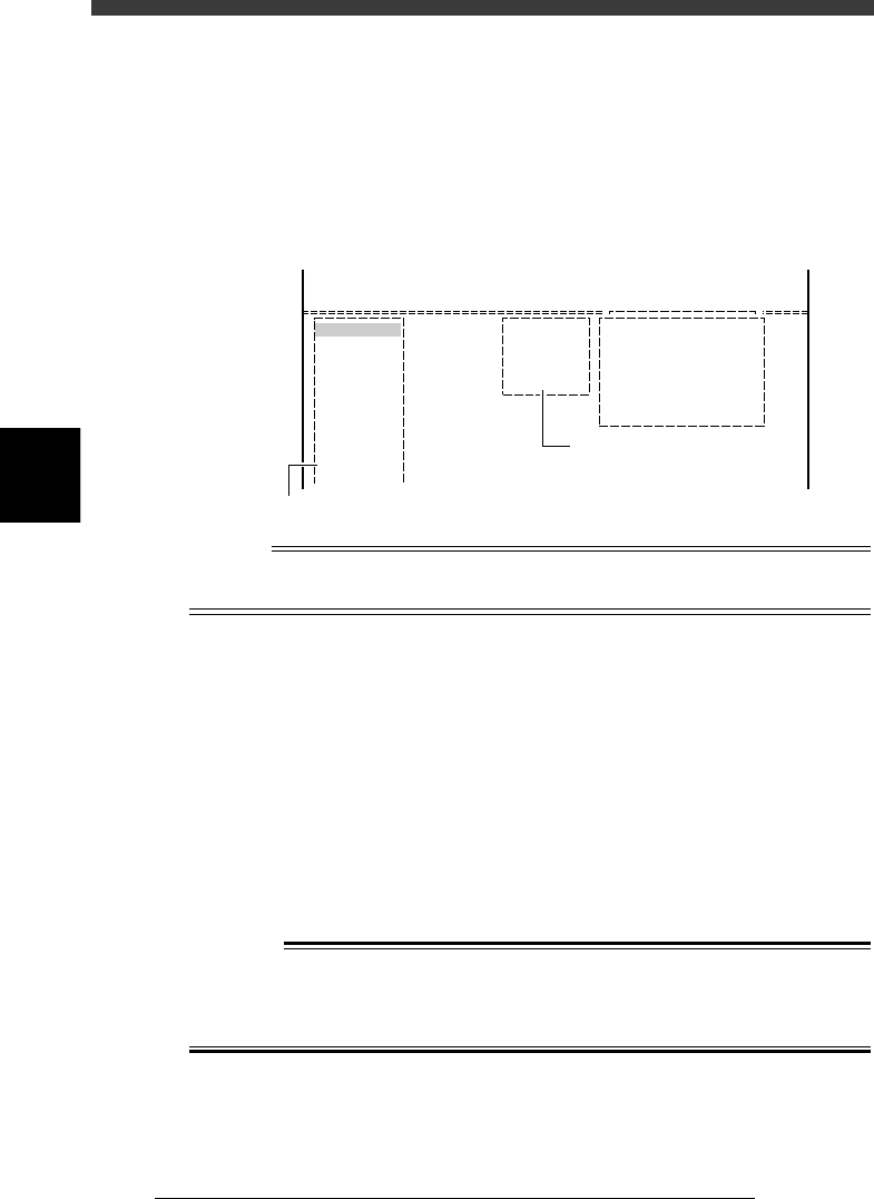
CONDITION monitor and RUNNING SPEED command
27406-C0-00
Condition
Speed 100
<<<APPLICATION>>> 1/OPERATION/M
<<MODE>> 1/RUNNING
<<COMMAND_LIST>>
RUNNING UTILITY
RUNNING SPEED [SPEED]
Speed = 100
Speed = 80
Speed = 60
Speed = 40
Speed = 20
D/INITILIZE
Displays current running speed
Select desired speed
Reference
The operation speed is preset in 5 steps from Speed 1 to Speed 5. If you want to change
these settings, use the <B2 RUNNING SPEED> command in MANUAL mode.
5
Start operation.
1. Release the emergency stop button and press the [READY] key.
2. Check the surrounding area for safety, then press the [RUN] key on the
YPU (twice) or operation panel, or execute the <1/1/A2 AUTO
RUNNING> command.
3. If the alert message for changing the conveyor width appears, check
safety again and press the [ENTER] key or [RUN] key.
The W-axis moves to set the proper PCB width and the machine is now
ready to receive a PCB.
4. When the entrance sensor detects a PCB, the conveyor motor begins to
rotate to carry the PCB to the mounting position and the machine starts
mounting components.
w
WARNING
A DANGEROUS SITUATION CAN OCCUR IF ANY PART OF THE BODY
ENTERS THE MOVEMENT RANGE OF THE HEAD ASSEMBLY DURING
OPERATION (GREEN WARNING LAMP IS LIT). BE SURE TO STAY OUT OF
THE MOVEMENT RANGE DURING OPERATION.