YV180X_Ope_E.pdf - 第189页
5 -113 EPD8013110 Operation Chapter 5 5 Creating the PCB data 9.2 Setting optimization conditions 1 Select <2/2/A4 CONDITION SETTING> and press the [ENTER] key . The DA T A GENERA T OR CONDITION selection box then …
5
-112
EPD8013110
Operation
Chapter 5
5
Creating the PCB data
9.1 Selecting the data
1 Select the data to be optimized.
Enter the DATA_GENERATOR mode, then select <2/2/A1 OBJECT
SELECTION> and press the [ENTER] key. The OBJECT SELECTION box
then appears.
OBJECT SELECTION box
27542-C0-00
<<<APPLICATION>>>
<<MODE>>
<COMMAND LIST> A/SETTING&RUN
OBJECT SELECTION
PCB SELECTION
FIXED PCB SELECTION
FIXED COMP. SEL
LOAD LAST SELECTION
QUIT
DATA GENERATOR OBJECT
PCB NAME
FIXED PCB
NZL. COND.
BLK. CONV.
FDR. POS.
A1 OBJECT SELECTION
NON
FREE
0 : NO
0 : NO
2/DATA/M
2/DATA GENERATOR
This menu box appears when
the <A1 OBJECT SELECTION>
command is executed.
The current data generator conditions
are displayed when the <2/2/A1 SETTING&RUN>
command is executed.
2 Select “PCB SELECTION” and press the [ENTER] key.
A list of registered PCB names then appears.
PCB selection box
27543-C0-00
A/SETTING & RUN
A1 OBJECT SELECTION
OBJECT SELECTION
PCB SELECTION
pcb name
PCB 1 1998-08-07
3 Select the PCB data.
Select or enter the PCB name to be optimized and press the [ENTER] key.
The OBJECT SELECTION box then reappears.
4 Quit the settings.
Select “QUIT” from the OBJECT SELECTION box and press the [ENTER]
key. The PCB data to be optimized has now been selected.

5
-113
EPD8013110
Operation
Chapter 5
5
Creating the PCB data
9.2 Setting optimization conditions
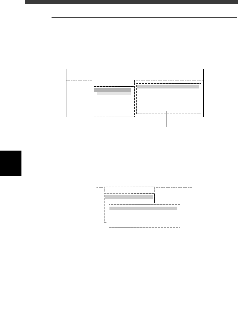
1 Select <2/2/A4 CONDITION SETTING> and press the
[ENTER] key.
The DATA GENERATOR CONDITION selection box then appears.
DATA GENERATOR CONDITION selection box
27544-C0-00
A/SETTING & RUN
A1 OBJECT SELECTION
A2 NOZZLE SETTING
DATA GENERATOR CONDITION
BLOCK CONVERSION CONDITION
FEEDER SET CONDITION
EDIT FEEDER PLATE
2 Set conditions.
Move the cursor to the item you want to set and press the [ENTER] key. A
list of conditions then appears. Set the desired condition while referring to
the description below. The settings marked with an asterisk (*) are typical
settings for single PCBs (not applicable to multi-block PCBs).
• BLOCK CONVERSION COND
0: NO *
This setting does not allow block conversion (See “2.2 Block conver-
sion” in Chapter 6.) Always select “NO” when not using a multi-block
PCB.
1: CONV. WITH NOTE DATA
Converts the multi-block PCB data into single PCB data while keeping
the original data. The converted data can be returned to the original
multi-block data.
2: CONV. WITHOUT NOTE DATA
Converts the multi-block PCB data into single PCB data without
keeping the original data. In this case, the data cannot be returned to
the original multi-block data.
3: CONV. BACK TO BLOCK
Reconverts the data which was converted with CONV. WITH NOTE
DATA into the original multi-block PCB data.
Reference
See “2.2 Block conversion” in Chapter 6 for detailed information about “block conver-
sion”.

5
-114
EPD8013110
Operation
Chapter 5
5
Creating the PCB data
• FEEDER SET CONDITION
0: NO
No mount data (mounting sequence, head selection and feeder set
position) is optimized.
1: ALL FEEDERS FIXED
The mounting sequence and head selection are optimized, but the
feeder set position is not optimized.
2: NO SET POS. FEEDERS MOVE
In addition to optimizing the mounting sequence and head selection,
the optimum feeder set number is assigned only to the component data
whose feeder position is unspecified (Feeder Set No. in the Component
Info. is set to “0”.)
3: MOVE WITHIN TABLE
In addition to optimizing the mounting sequence and head selection,
the optimum feeder set number is assigned all component data within
the front feeder plate when a feeder set number on the front feeder
plate was entered in the “Feeder Set No. column in the Component
Info, or within the rear plate when a feeder set number on the rear
feeder plate was entered in the “Feeder Set No. column in the Compo-
nent Info,
4: ALL FEEDERS MOVE*
In addition to optimizing the mounting sequence and head selection,
the optimum feeder set number is assigned to all component data
registered in the Component Info.
5: MOVE + FIXED COMP. MATCH
This setting allows performing the operations of “ALL FEEDERS MOVE”
and static component matching. (Refer to “4. Static components” in
Chapter 6 for detailed information.) This is invalid when static compo-
nents are not used.
• EDIT FEEDER PLATE
Here you can specify the feeder plate which should be selected
preferentially with data optimization.
EDIT FEEDER PLATE box
27545-C0-00
EDIT FEEDER PLATE
machine
Front plate
Use the [Space] [INS] or [DEL]
to make setting.