YV180X_Ope_E.pdf - 第171页
5 -95 EPD8013110 Operation Chapter 5 5 Creating the PCB data e Save the data. When settings are complete, press the [ESC] key twice to exit the current edit screen, then select <2/1/D8 SA VE PCB DA T A> and press t…

5
-94
EPD8013110
Operation
Chapter 5
5
Creating the PCB data
• Trans-Height
After components are mounted, the machine permits the conveyor to
carry out the PCB when the push-up unit is lowered. If components
have already been mounted on the reverse side of the PCB, the push-
up unit must be lowered sufficiently to avoid interference from push-
up pins with those components. This parameter specifies the height of
the push-up unit at which the conveyor is allowed to carry out each
type of PCB. Enter the distance in millimeters from the point where
the push-up unit is raised to clamp the PCB. This distance can be 3 to
30mm.
• Conv. Timer
Set to “0.0” sec. for normal shape PCBs. If specially configured PCBs
(for example, PCBs with cutout parts or through-holes) are used and
the exit sensor cannot detect them reliably, try setting this timer in the
range of 0.0 to 9.9 sec. The conveyor motor continues turning for the
specified time even after the PCB sensor turns off.
• Precede Pick
When this is set to “Use”, the head assembly starts moving to pick up
and recognize components as soon as the preceding PCB has been
carried out and the next PCB is carried in. This will shorten the cycle
time.
• Conv. Y Speed
This parameter specifies the conveyor Y-axis (YT-axis) moving speed.
Set to “FAST” in most cases. If the mounted components move or
slide on the PCB due to the YT-axis movement, set this parameter to a
slower speed.
• Local Fiduc.
Set to “Use” when using the local fiducial correcting function, and
“NotUse” when not using this function. This parameter is available
only when the data is input in “Fidu. Info.” in the main window
menu. Refer to “5. Using the fiducial functions” in Chapter 6 for more
details.
• Local Badmark
Set to “Use” when using the local badmark function, and “NotUse”
when not using this function. This parameter is available only when
the data is input in “Local BadMrkInfo.” in the main window menu.
Refer to “6. Using the badmark functions” in Chapter 6 for more
details.
• Retry Seq.
The retry sequence can be selected from the following methods.
“Group” : Retry is repeated with the head which caused an error,
until component mounting specified as one group is
complete.
“Block” : Retry is performed with the head which caused an error
after component mounting in one block is complete.
“Auto” : Retry is performed with any free head after component
mounting in one block is complete.
• Sp. Function
This parameter is not displayed on standard machines. If the machine
has a special function, set to “Use” when using it, or “NotUse” when
not using.

5
-95
EPD8013110
Operation
Chapter 5
5
Creating the PCB data
e Save the data.
When settings are complete, press the [ESC] key twice to exit the current
edit screen, then select <2/1/D8 SAVE PCB DATA> and press the [ENTER]
key.
5
-96
EPD8013110
Operation
Chapter 5
5
Creating the PCB data
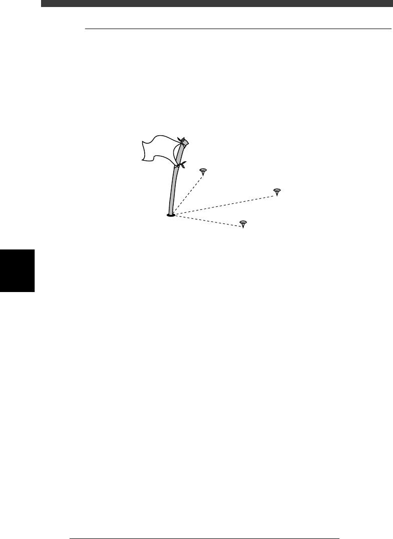
6.2 PCB origin
The reference point for the XY coordinates on a PCB is called the PCB
origin. The PCB origin is specified by the “PCB Origin” parameter in the
PCB Information.
The PCB origin must always be set since the PCB mark positions, compo-
nent mounting positions and the block repeat positions (refer to Chapter 6)
are specified by their coordinates relative to the PCB origin.
PCB origin
23541-C0-00
Mark position
Component
mounting positio
n
Block repeat
PCB
origin