YV180X_Ope_E.pdf - 第76页
4 -37 Operation Chapter 4 4 Daily operation EPD8013110 9.2 Editing mount flags The HALFW A Y CONTINUE command can also be used to perform mounting for a specific mounting point by specifying the mount data number . For e…
4
-36
4
Operation
Chapter 4
4
Daily operation
EPD8013110
9.1 Loading the saved data
Even when you have reset the mounting operation during PCB production,
the machine stores the mounting operation data that was in progress. You
can load that data by executing the HALFWAY CONTINUE command to
resume operation from the stopped point. Since the last mounting data
including error information is stored, mounting restarts from the points at
which errors occurred.
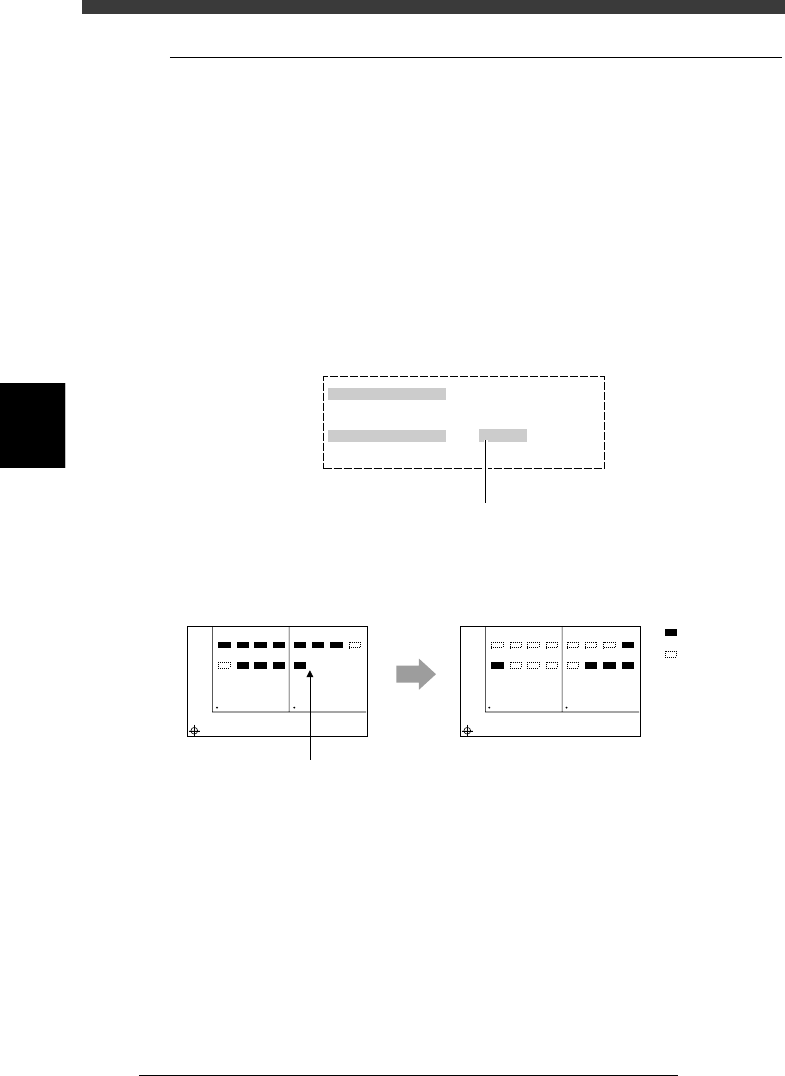
To load the saved data, select “LOAD SAVED CONDITION” from the
HALFWAY CONTINUE menu box and press the [ENTER] key. The Saved
Information box then appears as shown below. Set “Do you want to load
this?” to “EXECUTE”.
Setting to “EXECUTE” in the Saved Information box
27418-C0-00
Saved Information
Date & Time
Pcb name
Do you want to load this?
Select by [SPACE], press [ENTER] key.
1998-11-17 14 : 27 : 27
TEST
EXECUTE
Press the [Space], [INS] or [DEL] ke
y
to set this parameter to "EXECUTE".
Actual mounting operation
23416-C0-00
Automatic
operation restarts
after loading
the stored data.
1
5
BLOCK NO.1
BLOCK NO.2
2
6
3
7
4
8
1
5
2
6
3
7
4
8
1
5
BLOCK NO.1
BLOCK NO.2
2
6
3
7
4
8
1
5
2
6
3
7
4
8
: Mounted
: Not mounte
d
Reset and restart
4
-37
Operation
Chapter 4
4
Daily operation
EPD8013110
9.2 Editing mount flags
The HALFWAY CONTINUE command can also be used to perform
mounting for a specific mounting point by specifying the mount data
number. For example, when you have paused mounting operation and reset
the mounting data, you can check the flag in each point indicating whether
mounting has been completed and edit it as necessary.
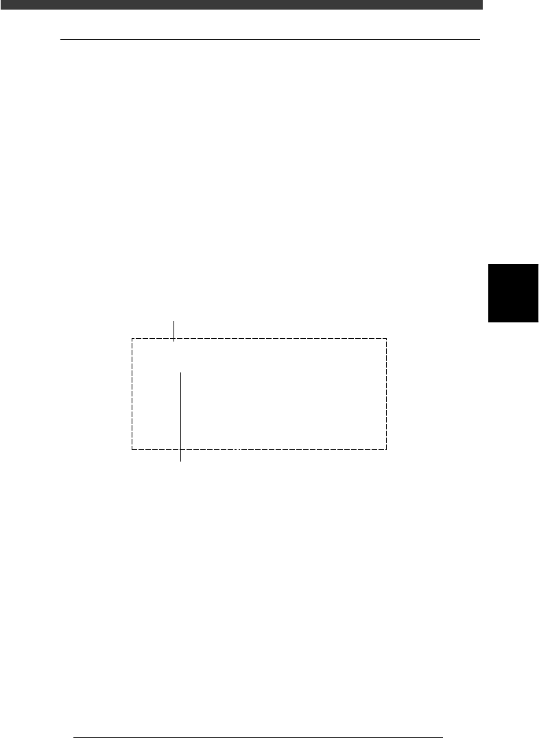
To edit these flags, set “LOAD SAVED CONDITION” as with the previous
section (“9.1 Loading the saved data”), and then select “MNT FLAG
EDITOR” from the HALFWAY CONTINUE menu box and press the
[ENTER] key. The mount flag edit box then appears as shown below. Edit
the flags as necessary. When the block repeat function is used, the mount
data for each block can also be edited.
Note that this function is used only for the first PCB, with routine mount-
ing operation beginning from the next PCB.
Mount flag edit screen
27419-C0-00
Blockt No.
Mount No.
Flags
Table No.
MountData
Component
| | | |
10 20 30 40
1
000---000
(0 : Finish - : Not Finish X : Skip)
Comment : C2125
X, Y, R : X= 71.00 , Y= 15.00 , R= -90.00
Name : C2125
No. : 1
Setno. : 40
Select the mount data No. with the right/left arrow keys, then
set the flag to “-” for the mount data No. you want to use to
perform mounting, and to “0” when you do not want to perform,
using the [Space], [DEL] or [INS] key.
To switch the block No., press the up/down arrow keys.

Chapter 5
Creating the PCB data
continued...
1. Overview ............................................................................. 5-3
2. Registering and selecting the PCB name............................... 5-5
2.1 Registering PCB names ............................................................. 5-6
2.2 Selecting the PCB name ........................................................... 5-8
3. Creating the component information ................................. 5-10
3.1 Creating procedure................................................................. 5-12
3.2 Various parameter settings ...................................................... 5-15
3.3 Chip components ................................................................... 5-16
3.3.1 Standard chip components
(box type chip resistors and capacitors) 5-16
3.3.2 Melf components (cylindrical components) 5-23
3.4 IC components ....................................................................... 5-27
3.4.1 Mini-mold transistor/SOT 5-27
3.4.2 SOP components 5-32
3.4.3 QFP components 5-37
3.5 Ball lead components ............................................................. 5-42
3.5.1 Simple BGA 5-42
3.5.2 BGA components (BGA setting) 5-46
3.6 Connector components .......................................................... 5-54
3.6.1 Connectors 5-54
3.7 Adjust Assistant commands .................................................... 5-58
3.8 Setting the stick feeder component data ................................. 5-65
3.8.1 When optimizing the feeder set positions 5-65
3.8.2 When not optimizing the feeder set positions 5-69
3.9 Registration location of component data ................................ 5-71
4. Creating the mark information ........................................... 5-72
4.1 Creating procedure................................................................. 5-74
4.2 Various parameter settings ...................................................... 5-76
4.3 Adjust Assistant commands .................................................... 5-82
5. Clamping the PCB .............................................................. 5-86
This chapter explains the basic procedures for creating or editing
PCB data and also making test-mount of components in order to
check the PCB data.