YV180X_Ope_E.pdf - 第90页
5 -14 EPD8008100 Operation Chapter 5 5 Creating the PCB data 5 Set necessary parameters in the sub-windows. Press the [T AB] key to move the cursor into the sub-window and set other parameters as necessary . For more det…
5
-13
EPD8008100
Operation
Chapter 5
5
Creating the PCB data
2. A list of data registered in the database appears, so select the data of
the same component or the most similar component in shape and press
the [ENTER] key to make a copy.
The selected database No. is enteered in the DataBase Number column
in the BASIC INFO. sub-window. At the same time, various parameters
of the selected component are copied. Press any key to return to the
previous screen.
Database No. selection screen
27508-C0-00
1
2
3
4
<<<APPLICATION>>>
<<MODE>> 1/EDIT_DATA
<COMMAND_LIST>
A/DISPLAY
A3
2/DATA/M
503
500
501
502
503
R1005
R1608
R2125
R3216
Database No. :
Database No.
Component name
Selected database No. is
copied here automatically.
Reference
You can copy the database information without using the <2/1/A3 VIEW DATABASE
NO.> command as follows:
1. Press the [TAB] key to move the cursor to the Database No. column in the BASIC
INFO. sub-window.
2. Enter the database number you want to copy from.
3. Press the [F7] key to run the SET FROM DATABASE command, and the information
onthe specified database number is then copied.
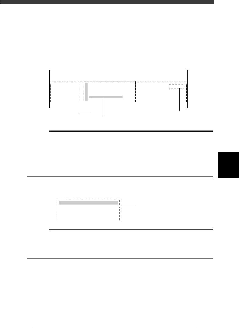
Database No. in BASIC INFO. sub-window
27509-C0-00
1.BASIC INFO.
Database No. : 502
Enter the database No.
to be copied and press
the [F7] key.
Reference
If data is registered in the database with numbers 1001 to 1600, you can redisplay all
these pieces of data from 1001 in alphabetical order by placing the cursor on the <A3
VIEW DATABASE NO.> command and pressing the [SHIFT] + [ENTER] keys.
For details on the database, refer to “3. Creating the user database” in Chapter 6.

5
-14
EPD8008100
Operation
Chapter 5
5
Creating the PCB data
5 Set necessary parameters in the sub-windows.
Press the [TAB] key to move the cursor into the sub-window and set other
parameters as necessary. For more details, refer to the next sections “3.2”
to “3.7” in this chapter. (To switch the sub-windows, press the [F4] key.)
Reference
When using stick feeders, refer to “3.8 Setting the stick feeder component data” in this
chapter.
6 Run the Adjust Assistant.
Press the [F6] key or run the <2/1B1 ADJUST ASSISTANT> command to
enter the Adjust Assistant mode.
The commands in the Adjust Assistant mode are used to check or optimize
the data copied or registered. (Refer to “3.7 Adjust Assistant commands” in
this chapter for more details.)
7 Save the PCB data.
Exit the Adjust Assistant mode, then press the [ESC] key twice, select <2/1/
D8 SAVE PCB DATA> and press the [ENTER] key.
8 Repeat the above steps for other components.
Use the same procedure from Step 2 to register all components to be
mounted on the PCB.
5
-15
EPD8008100
Operation
Chapter 5
5
Creating the PCB data
3.2 Various parameter settings
You must check and make necessary settings to the data copied from the
database, so that it matches the actual component you are going to use. The
subsequent sections from 3.3 to 3.6 explain how to set or check basic
parameters in the sub-windows according to typical component types.
Since precise settings can be made by actually recognizing each
component (with the Adjust Assistant commands described later in “3.7”),
the following description is for parameters which should be set manually in
each sub-window. For parameters not explained here, refer to the help
message which appears by pressing the [F1] key.
n
NOTE
When you use the component data copied from the YAMAHA database, first use the default
settings and then adjust or optimize them while checking the recognition status monitored
with the Adjust Assistant commands (described in “3.7” in this chapter). However,
parameters such as “Feeder Type” and Feeder Set No.” should be set to match the actual
machine.
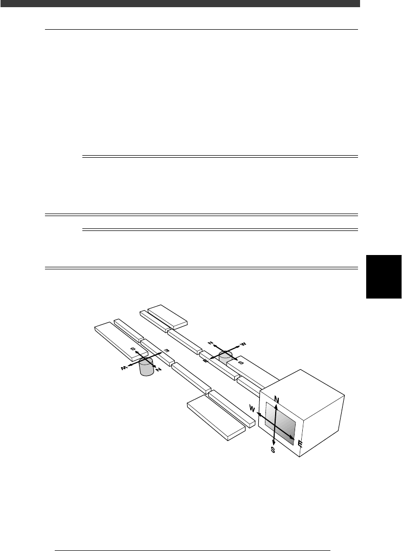
Reference
When making parameter settings, you will notice four kinds of alphabet letters “N, S, E
and W” which are indicated following certain parameters. These letters stand for the
directions in which the component is recognized with a vision system.
Component recognition directions
23507-D8-00
Vision display
A-table multi-vision camera
B-table multi-vision camera