YV180X_Ope_E.pdf - 第188页
5 -112 EPD8013110 Operation Chapter 5 5 Creating the PCB data 9.1 Selecting the data 1 Select the data to be optimized. Enter the DA T A_GENERA T OR mode, then select <2/2/A1 OBJECT SELECTION> and press the [ENTER]…
5
-111
EPD8013110
Operation
Chapter 5
5
Creating the PCB data
9. Data optimization
PCB production data you have created can be automatically optimized in
the <2/2/DATA_GENERATOR> mode, so that the PCB data can be used
more efficiently with a minimum cycle time.
For example, to optimize the PCB data on the feeder set position, head
number and mounting sequence, follow the procedure explained in this
section.
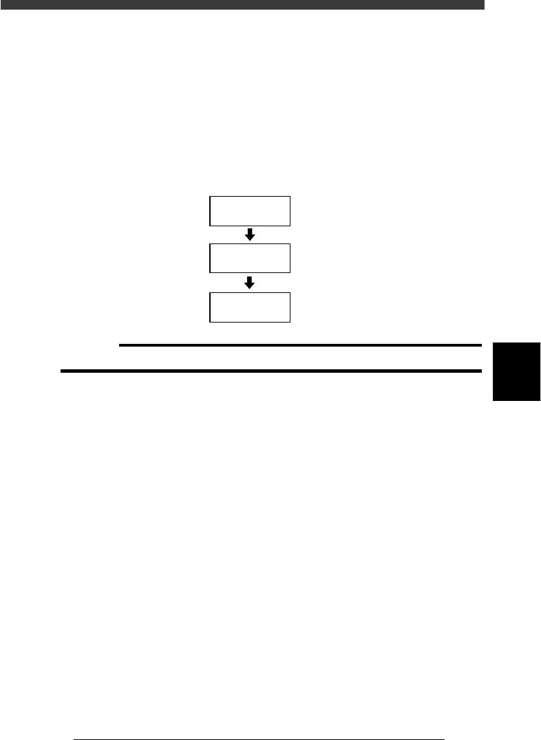
Data optimization flow
23551-C0-00
Set conditions
Select data to be
optimized
Optimize data
9.2
☞
9.1
☞
9.3
☞
c
CAUTION
The PCB data is changed when data optimization is performed.
5
-112
EPD8013110
Operation
Chapter 5
5
Creating the PCB data
9.1 Selecting the data
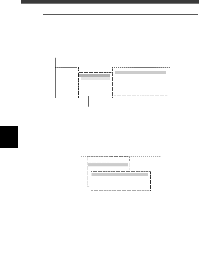
1 Select the data to be optimized.
Enter the DATA_GENERATOR mode, then select <2/2/A1 OBJECT
SELECTION> and press the [ENTER] key. The OBJECT SELECTION box
then appears.
OBJECT SELECTION box
27542-C0-00
<<<APPLICATION>>>
<<MODE>>
<COMMAND LIST> A/SETTING&RUN
OBJECT SELECTION
PCB SELECTION
FIXED PCB SELECTION
FIXED COMP. SEL
LOAD LAST SELECTION
QUIT
DATA GENERATOR OBJECT
PCB NAME
FIXED PCB
NZL. COND.
BLK. CONV.
FDR. POS.
A1 OBJECT SELECTION
NON
FREE
0 : NO
0 : NO
2/DATA/M
2/DATA GENERATOR
This menu box appears when
the <A1 OBJECT SELECTION>
command is executed.
The current data generator conditions
are displayed when the <2/2/A1 SETTING&RUN>
command is executed.
2 Select “PCB SELECTION” and press the [ENTER] key.
A list of registered PCB names then appears.
PCB selection box
27543-C0-00
A/SETTING & RUN
A1 OBJECT SELECTION
OBJECT SELECTION
PCB SELECTION
pcb name
PCB 1 1998-08-07
3 Select the PCB data.
Select or enter the PCB name to be optimized and press the [ENTER] key.
The OBJECT SELECTION box then reappears.
4 Quit the settings.
Select “QUIT” from the OBJECT SELECTION box and press the [ENTER]
key. The PCB data to be optimized has now been selected.

5
-113
EPD8013110
Operation
Chapter 5
5
Creating the PCB data
9.2 Setting optimization conditions
1 Select <2/2/A4 CONDITION SETTING> and press the
[ENTER] key.
The DATA GENERATOR CONDITION selection box then appears.
DATA GENERATOR CONDITION selection box
27544-C0-00
A/SETTING & RUN
A1 OBJECT SELECTION
A2 NOZZLE SETTING
DATA GENERATOR CONDITION
BLOCK CONVERSION CONDITION
FEEDER SET CONDITION
EDIT FEEDER PLATE
2 Set conditions.
Move the cursor to the item you want to set and press the [ENTER] key. A
list of conditions then appears. Set the desired condition while referring to
the description below. The settings marked with an asterisk (*) are typical
settings for single PCBs (not applicable to multi-block PCBs).
• BLOCK CONVERSION COND
0: NO *
This setting does not allow block conversion (See “2.2 Block conver-
sion” in Chapter 6.) Always select “NO” when not using a multi-block
PCB.
1: CONV. WITH NOTE DATA
Converts the multi-block PCB data into single PCB data while keeping
the original data. The converted data can be returned to the original
multi-block data.
2: CONV. WITHOUT NOTE DATA
Converts the multi-block PCB data into single PCB data without
keeping the original data. In this case, the data cannot be returned to
the original multi-block data.
3: CONV. BACK TO BLOCK
Reconverts the data which was converted with CONV. WITH NOTE
DATA into the original multi-block PCB data.
Reference
See “2.2 Block conversion” in Chapter 6 for detailed information about “block conver-
sion”.